Chery Tiggo. Manual - part 354


  Index      Chery     Chery Tiggo - service repair manual 2009 year


Search            


Content   ..  352  353  354  355   ..


Chery Tiggo. Manual - part 354


Front Brake Caliper

Description

The calipers are a single piston type. The calipers are free to slide laterally on the anchor, this allows continuous
compensation for lining wear. The calipers are directly bolted to the wheel hub with mounting bolts. The brake rotor
dust shield is mounted to the hub.

Operation

When the brakes are applied, fluid pressure is exerted against the caliper piston. The fluid pressure is exerted
equally and in all directions. This means pressure exerted against the caliper piston and within the caliper bores will
be equal. Fluid pressure applied to the pistons is transmitted directly to the inboard brake pad. This forces the pad

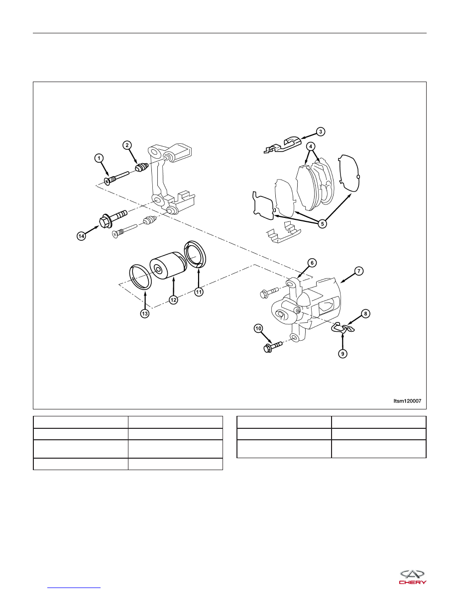
1 - Locating Guide Rod

5 - Lining Damper

2 - Dust Cap

6 - Brake Caliper Bracket

3 - Brake Gasket

7 - Brake Caliper Body
Connecting Bolt

4 - Brake Lining Assembly

8 - Bleeding Screw

9 - Dust Cover

12 - Piston

10 - Brake Caliper

13 - Piston Seal

11 - Piston Dust Cap

14 - Brake Caliper Bracket
Bolt

ON-VEHICLE SERVICE

LTSM120007


lining against the inner surface of the disc brake rotor. At the same time, fluid pressure within the piston bore forces
the caliper to slide inward on the slide pins. This action brings the outboard brake pad lining into contact with the
outer surface of the disc brake rotor.

Removal & Installation

1. Using a brake pedal holding tool, depress the brake pedal past its first 25 mm of travel and hold it in this posi-

tion. This will isolate the master cylinder from the brake hydraulic system and will not allow the brake fluid to
drain out of the master cylinder reservoir when the lines are opened.

2. Raise and support the vehicle.

3. Remove the wheel mounting nuts and the tire and wheel assembly.

(Tighten: Wheel mounting nuts to 110 N·m)

4. Using a large C-clamp (2), push the caliper piston

to an adequate depth to remove the brake caliper
(1) from the brake disc.

5. Remove the front brake hose from the front brake caliper.

(Tighten: Front caliper brake hose to 19 N·m)

6. Remove the front caliper guide pin bolts (1).

(Tighten: Front caliper guide pin bolts to 23 N·m)

7. Slide the front brake caliper from the disc brake adapter bracket and remove.

8. Installation is in the reverse order of removal.

Installation Notes:
• Completely retract the caliper piston back into the bore of the caliper.

• After installation, bleed the caliper as necessary.

Rear Brake Caliper

Description

The rear disc brakes consist of fixed single piston style calipers and solid rotors. The rear caliper is mounted to the
rear wheel hub. The calipers are directly bolted to the wheel hub with mounting bolts. The disc brake rotor dust shield
is mounted to the hub. The brake rotor has a built in drum used for the parking brakes. The parking brake shoes are
mounted to the wheel hub.

ON-VEHICLE SERVICE

LTSM120009

LTSM120008

12


Operation

When the brakes are applied, fluid pressure is exerted against the caliper piston. The fluid pressure is exerted
equally and in all directions. This means pressure exerted against the caliper piston and within the caliper bores will
be equal. Fluid pressure applied to the pistons is transmitted directly to the inboard brake pad. This forces the pad
lining against the inner surface of the brake rotor. At the same time, fluid pressure within the piston bore forces the
caliper to slide inward on the slide pins. This action brings the outboard brake pad lining into contact with the outer
surface of the disc brake rotor.

Removal & Installation

1. Using a brake pedal holding tool, depress the brake pedal past its first 25 mm of travel and hold it in this posi-

tion. This will isolate the master cylinder from the brake hydraulic system and will not allow the brake fluid to
drain out of the master cylinder reservoir when the lines are opened.

2. Raise and support the vehicle.

3. Remove the wheel mounting nuts and the tire and wheel assembly.

(Tighten: Wheel mounting nuts to 110 N·m)

4. Remove the banjo bolt connecting the brake hose to the rear brake caliper.

(Tighten: Rear caliper banjo bolt to 20 N·m)

5. Remove the rear caliper guide pin bolts.

(Tighten: Rear caliper guide pin bolts to 23 N·m)

6. Remove rear brake caliper adapter mounting bolts

(1).
(Tighten: Rear brake caliper adapter mounting bolts
to 63 N·m)

7. Slide the rear brake caliper from the disc brake

adapter bracket and remove.

8. Installation is in the reverse order of removal.

Installation Notes:
• Completely retract the caliper piston back into the bore of the caliper.

• After installation bleed the caliper as necessary.

ON-VEHICLE SERVICE

LTSM120017


Front Brake Rotor

Removal & Installation

1. Raise and support the vehicle.

2. Remove the wheel mounting nuts and the tire and wheel assembly.

(Tighten: Wheel mounting nuts to 110 N·m)

3. Remove the front caliper (See Front Caliper

Removal & Installation in Section 12 Brakes).

4. Remove the front brake rotor locating screws (1).

(Tighten: Front brake rotor locating screws to 6-12
N·m)

5. Slide the front brake rotor off the hub and bearing.

6. Installation is in the reverse order of removal.

Inspection

Excessive runout or wobble in a rotor can increase pedal travel due to piston knock-back. This increases guide pin
sleeve wear due to the tendency of the caliper to follow the rotor wobble.

Braking Surface Inspection

Light braking surface scoring and wear is acceptable. If heavy scoring or warping is evident, the rotor must be resur-
faced or replaced. Excessive wear and scoring of the rotor can cause improper lining contact on the rotor’s braking
surface. If the ridges on the rotor are not removed before new brake pads are installed, improper wear of the shoes
will result. Some discoloration or wear of the rotor surface is normal and does not require resurfacing when linings
are replaced. If cracks or burned spots are evident, the rotor must be replaced.

Rotor Minimum Thickness

Measure the rotor thickness (1) at the center of the
brake pad contact surface. Replace the rotor (2) if it is
worn below minimum thickness or if machining the rotor
will cause its thickness to fall below specifications.

CAUTION:
Do not machine the rotor if it will cause the rotor to fall below minimum thickness.

ON-VEHICLE SERVICE

LTSM120022

BESM120004

12


Content   ..  352  353  354  355   ..