Chery Tiggo. Manual - part 353


  Index      Chery     Chery Tiggo - service repair manual 2009 year


Search            


Content   ..  351  352  353  354   ..


Chery Tiggo. Manual - part 353


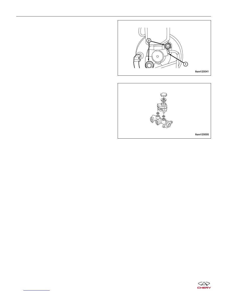
9. Disconnect the brake tubes (1) and remove the

nuts (2) attaching the master cylinder to the power
brake booster.
(Tighten: Master cylinder mounting nuts to 23 N·m)

10. Slide the master cylinder straight out of the power

brake booster.

11. Installation is in the reverse order of removal.

NOTE :
After installation, bleed the master cylinder or bleed the entire brake system as necessary.

Power Brake Booster - LHD

Description

The power brake booster is mounted in the engine compartment on the left side of the dash panel. The master
cylinder is bolted to the front of the booster.

Operation

A vacuum line connects the check valve to engine source vacuum. The booster input rod extends through the dash
panel and connects to the brake pedal.

Removal & Installation

CAUTION:
The vacuum in the power brake booster must be pumped down before removing the master cyl-
inder to avoid damaging the master cylinder and to prevent the booster from sucking in any con-
tamination. This can be done by pumping the brake pedal while the engine is not running until a
firm brake pedal is achieved.

1. Remove the master cylinder (See Master Cylinder Removal & Installation in Section 12 Brakes).

ON-VEHICLE SERVICE

LTSM120041

LTSM120005


2. Remove the spring-type cotter pin (2) and clevis

pin (1) from the brake booster rod (3).

3. Remove the nuts and bolts (1) attaching the power

brake booster to the brake pedal bracket.
(Tighten: Brake pedal/Power brake booster mount-
ing nuts and bolts to 25 N·m)

4. Remove the brake pedal bracket.

5. Disconnect the vacuum hose (1) from the check

valve on the power brake booster.

6. Slide the power brake booster (1) forward until its

mounting studs clear the dash panel, then remove
it through the engine compartment.

7. Installation is in the reverse order of removal.

ON-VEHICLE SERVICE

BESM120009

LTSM120006

LTSM120004

BESM120028

12


Power Brake Booster - RHD

Description

The power brake booster is mounted in the engine compartment on the right side of the dash panel. The master
cylinder is bolted to the front of the booster.

Operation

A vacuum line connects the check value to engine source vacuum. The booster input rod extends through the dash
panel and connects to the brake pedal.

Removal & Installation

CAUTION:
The vacuum in the power brake booster must be pumped down before removing the master cyl-
inder to avoid damaging the master cylinder and to prevent the booster from sucking in any con-
tamination. This can be done by pumping the brake pedal while the engine is not running until a
firm brake pedal is achieved.

1. Remove the master cylinder (See Master Cylinder Removal & Installation in Section 12 Brakes).

2. Remove the spring-type cotter pin (2) and clevis

pin (1) from the brake booster rod (3).

3. Remove the nuts and bolts (1) attaching the power

brake booster to the brake pedal bracket.
(Tighten: Brake pedal/Power brake booster mount-
ing nuts and bolts to 25 N·m)

4. Remove the brake pedal bracket.

ON-VEHICLE SERVICE

BESM120009

LTSM120006


5. Disconnect the vacuum hose (1) from the check

valve on the power brake booster.

6. Slide the power brake booster forward until its mounting studs clear the dash panel, then remove it through the

engine compartment.

7. Installation is in the reverse order of removal.

ON-VEHICLE SERVICE

LTSM120004

12


Content   ..  351  352  353  354   ..