Chery Tiggo. Manual - part 339


  Index      Chery     Chery Tiggo - service repair manual 2009 year


Search            


Content   ..  337  338  339  340   ..


Chery Tiggo. Manual - part 339


8. Install the wheel assembly and install the wheel mounting nuts.

(Tighten: Wheel mounting nuts to 110 N·m)

Wheel Assembly

Description

Original equipment wheels are designed for operation up to the specified maximum vehicle capacity.

Inspect wheels for the following:

• Dents or cracks

• Damaged wheel bolt holes

• Air leaks from any area or surface of the rim

• Excessive run out

NOTE :
Do not attempt to repair a wheel by hammering, heating or welding.

NOTE :
The wheel nuts are designed for specific applications. Do not use replacement bolts with a different design or lesser
quality.

Removal & Installation

1. Raise and support the vehicle.

2. If the vehicle is equipped with wheel center caps that cover the wheel nuts, remove the cap with an appropriate

removal tool utilizing the notch located between the wheel and the outer edge of the cap.

NOTE: Use care not to damage the finish on the wheel.

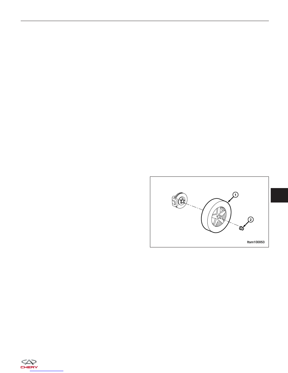
3. Remove the wheel mounting nuts (2) with a suit-

able tool and remove the wheel assembly (1).
(Tighten: Wheel mounting nuts to 110 N·m)

4. Installation is in the reverse order of removal.

Wheel Balance

Description

Balance the wheel assembly as necessary following the wheel balancer manufacturer’s instructions.

• Road test the vehicle for at least 5 miles.

• If the vibration persists, continue with Diagnosis & Testing procedure.

NOTE :
• Balance equipment must be calibrated and maintained per equipment manufacturer’s specifications.

• Wheel weight must fit the rim.

ON-VEHICLE SERVICE

LTSM100053

10


Wheel Balance Procedure

1. Raise and support the vehicle.

2. Remove the wheel mounting nuts and the wheel

assembly.

3. Perform a dynamic balance test.

NOTE :
A wheel requiring 5g or less of weight per side is con-
sidered to be within the proper specifications for a
wheel balance.

4. Install the appropriate wheel weights on the inner

(2) and outer (1) edges of the rim until the wheel is
balanced within specifications.

NOTE :
Not more than one wheel weight can be attached to
each side of the wheel, with its maximum weight not
exceeding 40g.

CAUTION:
Use caution not to damage wheel weights dur-
ing tire and wheel installation.

5. Install the wheel assembly and install the wheel

mounting nuts.
(Tighten: Wheel mounting nuts to 110 N·m)

Tire Rotation

Description

Tires on the front and rear operate at different loads and perform different steering, driving, and braking functions.
For these reasons they wear at unequal rates and tend to develop irregular wear patterns. These effects can be
reduced by rotating the tires at regular intervals.

The benefits of tire rotation are:

• Increase tread life

• Maintain traction levels

• A smooth, quiet ride

ON-VEHICLE SERVICE

BESM100020


Non-Directional Tires

The suggested method of tire rotation is shown. Other rotation methods can be used, but they will not provide all the
tire longevity benefits.

NOTE :
Only the four-tire rotation method may be used if the vehicle is equipped with a compact or temporary spare tire.

1. Raise and support the vehicle.

2. Remove the wheel mounting nuts and the wheel assembly.

3. Rotate the tire to the desired location.

CAUTION:
Use caution not to damage wheel weights during tire and wheel installation.

4. Install the wheel assembly and install the wheel mounting nuts.

(Tighten: Wheel mounting nuts to 110 N·m)

Directional Tires

Some vehicles may be fitted with special high-performance tires having a directional tread pattern. These tires are
designed to improve traction on wet pavement. To obtain the full benefits of this design, the tires must be installed so
that they rotate in the correct direction. This is indicated by arrows on the tire sidewalls. When being installed, extra
care is needed to ensure that this direction of rotation is maintained.

1. Remove the wheel mounting nuts and the wheel assembly.

2. Rotate the tire to the desired location.

CAUTION:
Use caution not to damage wheel weights during tire and wheel installation.

3. Install the wheel assembly and install the wheel mounting nuts.

(Tighten: Wheel mounting nuts to 110 N·m)

ON-VEHICLE SERVICE

PZSM100039T

10


STEERING

11

CONTENTS

page

Steering System . . . . . . . . . . . . . . . . . . . . . . . . . . . . . . . . . . . . . . . . . . . . . . . . . . . . . . . . . . . . . . . . . . . . . 11-1

Steering Column . . . . . . . . . . . . . . . . . . . . . . . . . . . . . . . . . . . . . . . . . . . . . . . . . . . . . . . . . . . . . . . . . . . . . 11-8

Steering Gear . . . . . . . . . . . . . . . . . . . . . . . . . . . . . . . . . . . . . . . . . . . . . . . . . . . . . . . . . . . . . . . . . . . . . . 11-18

Power Steering Pump . . . . . . . . . . . . . . . . . . . . . . . . . . . . . . . . . . . . . . . . . . . . . . . . . . . . . . . . . . . . . . . . 11-31

STEERING SYSTEM

GENERAL INFORMATION

11-2

Description

11-2

Operation

11-2

Specifications

11-3

Special Tools

11-3

DIAGNOSIS & TESTING

11-4

Power Steering Troubleshooting Chart

11-4

Power Steering Fluid Troubleshooting
Chart

11-5

ON-VEHICLE SERVICE

11-6

Power Steering Filling and Flushing

11-6

Filling

11-6

Flushing

11-6

Inspection

11-7

11


Content   ..  337  338  339  340   ..