Chery Tiggo. Manual - part 337


  Index      Chery     Chery Tiggo - service repair manual 2009 year


Search            


Content   ..  335  336  337  338   ..


Chery Tiggo. Manual - part 337


ON-VEHICLE SERVICE

Front Wheel Alignment

Front Wheel Alignment Specifications

NOTE :
If the vehicle has been in an accident causing the front axle components to be damaged, the damaged components
must be replaced before performing a front wheel alignment.

FRONT WHEEL ALIGNMENT

FRONT WHEEL ALIGNMENT

PREFERRED SETTING

ACCEPTABLE RANGE

Camber

-51’

+9’ to -1°51’

Caster

+2°50’

+3°30’ to +2°5’

Inclination

+11°30’

+12°15’ to +10°45’

Toe-Individual

0’

+5’ to -5’

Front Axle Toe-In Adjustment

CAUTION:
Do not twist the inner tie rod steering gear boot (bellows) while turning the inner tie rod during
front toe-in adjustment. It may be necessary to remove the clamp where the boot meets the inner
tie rod.

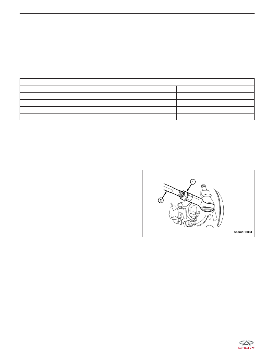
1. Loosen the tie rod adjusting jam nut (1).

(Tighten: Tie rod adjusting jam nut to 35 ± 3 N·m)

2. Grasp the inner tie rod shaft (2) and adjust the tie

rod end until the front toe-in is set to the proper
specification.

3. Make sure the inner tie rod steering gear boot is not twisted. If removed, reinstall the clamp where the boot

meets the inner tie rod.

4. Remove the alignment equipment.

5. Lower vehicle and jounce the front and rear of the vehicle.

Front Camber Adjustment

NOTE :
The front axle camber can not be adjusted. Replace the relative components if necessary.

BESM100031


Rear Wheel Alignment

Rear Wheel Alignment Specifications

NOTE :
If the vehicle has been in an accident causing the rear axle components to be damaged, the damaged components
must be replaced before performing a rear wheel alignment.

REAR WHEEL ALIGNMENT

REAR WHEEL ALIGNMENT

PREFERRED SETTING

ACCEPTABLE RANGE

Camber

-54’

-24’ to -1°24’

Toe-Individual

-5’

+5’ to -15’

Rear Axle Toe-In Adjustment

1. While holding the cam bolt stationary, loosen the

lower control arm mounting cam nut (1).
(Tighten: Lower control arm mounting cam nut to
80 - 100 N·m)

2. Rotate the cam bolt head left or right until the rear

wheel Toe-in for that rear wheel is set to the pre-
ferred specification.

3. While holding the cam bolt head stationary, tighten

the Toe-in link mounting cam bolt to the specified
torque.

ON-VEHICLE SERVICE

BESM100031

10


Rear Camber Adjustment

1. While holding the cam bolt stationary, loosen the

upper control arm bolt (1).
(Tighten: Upper control arm bolt to 80 - 100 N·m)

2. Rotate the cam bolt head left or right until the rear

wheel camber for that rear wheel is set to the pre-
ferred specification.

3. While holding the cam bolt head stationary, tighten

the upper control arm bolt to the specified torque.

ON-VEHICLE SERVICE

BESM100031


WHEELS AND TIRES

GENERAL INFORMATION

10-48

Description

10-48

Operation

10-48

Specifications

10-48

DIAGNOSIS & TESTING

10-50

Vehicle Inspection

10-50

Tire and Wheel Vibration

10-50

Tire Wear Patterns

10-50

Wheel Out-Of-Round Inspection

10-50

ON-VEHICLE SERVICE

10-51

Tire Repair

10-51

Description

10-51

Replacement Procedure

10-51

Repair Procedure

10-51

Wheel Assembly

10-52

Description

10-52

Removal & Installation

10-52

Wheel Balance

10-52

Description

10-52

Wheel Balance Procedure

10-53

Tire Rotation

10-53

Description

10-53

Non-Directional Tires

10-54

Directional Tires

10-54

10


Content   ..  335  336  337  338   ..