Chery Tiggo. Manual - part 330


  Index      Chery     Chery Tiggo - service repair manual 2009 year


Search            


Content   ..  328  329  330  331   ..


Chery Tiggo. Manual - part 330


Front Coil Spring

Description

A coil-over front strut assembly supports each front coil spring. The top of the strut assembly mounts to the strut
tower.

Operation

Coil springs are designed to store energy and subsequently release it and to absorb shock and maintain a force
between contacting surfaces. Coil springs are rated for specific vehicle applications.

NOTE :
Each component is serviced by removing the strut assembly from the vehicle and disassembling it. Coil springs are
rated separately for each corner or side of the vehicle depending on optional equipment and type of vehicle service.
If a coil spring requires replacement, be sure that it is replaced with a spring meeting the correct load rating for the
vehicle and its specific options.

Removal & Installation

CAUTION:
At no time when servicing a vehicle can a sheet metal screw, bolt or other metal fastener be
installed into the strut tower to take the place of an original plastic clamp. Also, do not drill holes
into the front strut tower for the installation of any metal fasteners into the strut tower area indi-
cated.

1. Raise and support the vehicle.

2. Remove the front strut assembly (See Front Strut Removal & Installation in Section 10 Suspension).

WARNING!

Do not remove the strut rod nut before the coil spring is properly compressed. The coil spring is held under
pressure. The coil spring must be compressed, removing spring tension from the upper mount and bearing,
before the strut rod nut is removed.

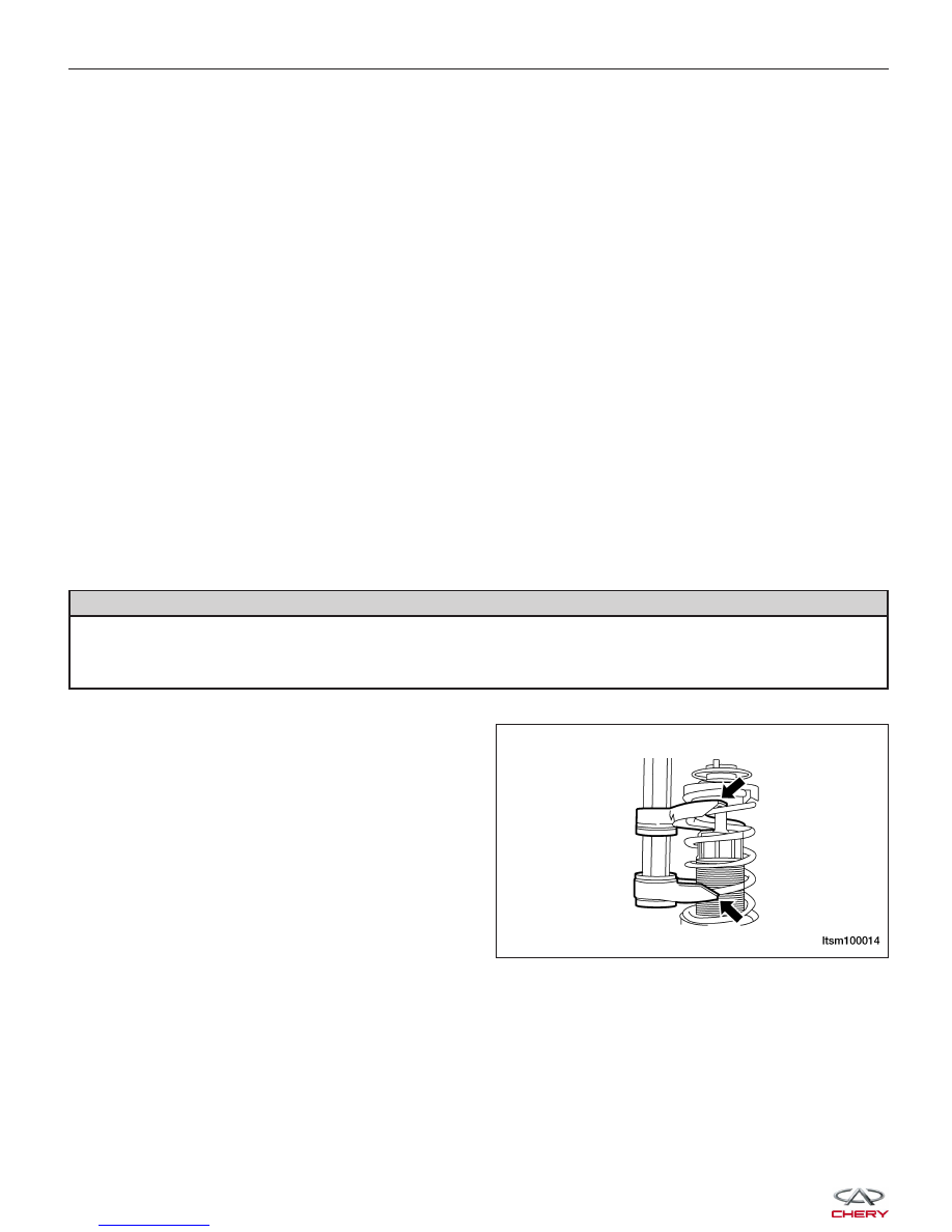
3. Position the strut assembly in the strut coil spring

compressor following the manufacturer’s instruc-
tions and set the lower and upper hooks of the
compressor on the coil spring.

4. Compress the coil spring until all coil spring tension

is removed from the upper mount and bearing.

5. Once the spring is sufficiently compressed, install the strut nut wrench on the strut rod nut.

6. Install a deep socket on the end of the strut rod.

ON-VEHICLE SERVICE

LTSM100014


7. While holding the strut rod, remove the nut using

the strut nut wrench.
(Tighten: Strut rod nut to 100 - 120 N·m)

8. Remove the lower spring isolator from the strut seat.

9. Remove the dust shield and jounce bumper.

10. Remove the upper mounting bracket.

11. Remove the upper spring seat and isolator.

12. Release the tension from the coil spring by backing off the compressor drive completely. Release the compressor

hooks and remove the coil spring.

13. Assembly is in the reverse order of disassembly.

Front Sub-Frame Assembly

Removal & Installation

WARNING!

Before removing the sub-frame assembly, properly support the engine and transaxle assembly.

1. Raise and support the vehicle.

2. Remove the wheel mounting nuts and the wheel assembly.

(Tighten: Wheel mounting nuts to 110 N·m)

3. Support the engine using an engine support fixture or suitable jack.

4. Remove the engine undercover and splash shields.

5. Remove the intermediate shaft lock bolt (1) that

connects to the steering gear.
(Tighten: Intermediate shaft lock nut to 25 - 30 N·m)

ON-VEHICLE SERVICE

LTSM100015

LTSM110008

10


6. Remove the nut (1) between the control arm and

the steering knuckle.
(Tighten: Control arm to steering knuckle nut to
120 ± 10 N·m)

7. Remove the wheel speed sensor mounting bolt (1).

(Tighten: Wheel speed sensor mounting bolt to 10
± 1 N·m)

8. Remove the wheel speed sensor and set it aside.

9. Remove the left and right front stabilizer bar links (See Front Stabilizer Bar Link Removal & Installation in Sec-

tion 10 Suspension).

10. Remove the nut (1) attaching the outer tie rod ends

to the steering knuckle on each side of the steering
rack.
(Tighten: Outer tie rod end nut to 35 N·m)

11. Remove the exhaust pipe assembly mounting bolts

(1).
(Tighten: Exhaust pipe assembly mounting bolts to
25 ± 3 N·m)

ON-VEHICLE SERVICE

LTSM100006

LTSM100045

LTSM110034

VISM110016


12. Remove the exhaust pipe assembly (See Exhaust Pipe Removal & Installation in Section 07 Exhaust).

13. Remove the high pressure and low pressure lines

(1) from the steering gear (drain steering fluid from
lines).
(Tighten: High pressure line to power steering
pump 27 - 33 N·m)
(Tighten: Low pressure line to power steering pump
27 - 33 N·m)

14. Remove the two bolts (1) between the steering

gearing and the sub-frame.
(Tighten: Steering gear to sub-frame bolts to 70 -
80 N·m)

ON-VEHICLE SERVICE

LTSM110007

LTSM100024

10


Content   ..  328  329  330  331   ..