Chery Tiggo. Manual - part 319


  Index      Chery     Chery Tiggo - service repair manual 2009 year


Search            


Content   ..  317  318  319  320   ..


Chery Tiggo. Manual - part 319


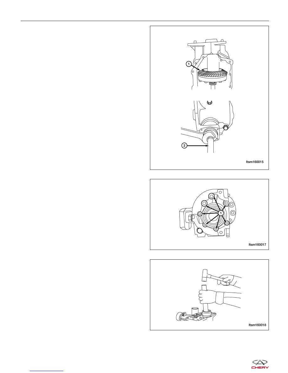
3. Lock up the drive gear (1) and loosen the driven

gear axle (2) locking nut.

4. Loosen the 7 bolts (1) and remove the right bear-

ing support components.
(Tighten: Transfer case right bearing support bolts
to 35 N·m)

5. Remove the input clutch and the drive gear.

Remove the retainer ring of the input clutch with
snap-ring pliers; punch the output end out of the
input clutch with a copper punch, and remove the
input clutch and the drive gear.

TRANSFER CASE UNIT REPAIR

LTSM160015

LTSM160017

LTSM160018


6. Remove the fluid seal of the input clutch.

Pry out the fluid seal with a slotted screwdriver.

Assembly

1. Put a standard-sized 1.4 mm adjusting shim from the front bearing driven gear axle into the transfer case hous-

ing. Press in the front outer bearing race of the driven gear axle, then the rear outer bearing race, and press the
front bearing of the driven gear axle into the driven gear axle; then put it into the collar and press in the rear
inner bearing race. Attach the locknut, and adjust the tightening torque of the driven gear by adjusting the locknut
until the driven gear axle can be driven with a torque of 1.0-1.5 N·m.

2. Assemble the flange axle.

Link the drive gear ring of the transfer case to the flange axle with a mounting bolt, tighten the bolt to 110 N·m.
Install the bearing to the left of the flange axle and the bearing to the left of the right bearing seat.

3. Choose the 2.4 mm standard-sized adjusting shim for the left bearing for the flange axle. Put the adjusting shim

for the right bearing for the flange axle, the outer bearing race to the left of the flange axle and the flange axle
into the transfer case.
Measure the distance (A) from the contact surface of the right bearing seat and the transfer case to the right
bearing seat and the left bearing’s right end surface.
Measure the distance (B) from the contact surface of the right bearing seat and the transfer case to the place
where the right and left bearings on the right bearing seat.

4. Calculate the thickness value of the adjusting gasket S = A - B.

5. Select the adjusting gasket: S + (0.05 - 0.10) mm.

6. Assembly of the right bearing seat.

Assemble the right bearing to the right bearing seat, install the retainer ring of the right bearing to the right
bearing seat, install the fluid seals to the left and right of the right bearing seat, install the O-ring and link the
right bearing seat to the transfer case housing with the bolt. Tighten the bolt to 35 N·m. The subassembly should
be able to rotate with 3.0-5.0 N·m torque.

7. Adjust the hypoid gear engagement: first, spread red lead powder on the teeth of the driven bevel gear so that

there will appear red prints on both working sides of the gear teeth of the driving bevel gear when turning it by
hand. If the gear pattern prints on both engaging sides of the drive gear ring is higher than the center of the gear
height near to the small end and occupy over 60% of the gear tooth width, then the pattern is correct; and the
backlash between various gear teeth should fall between 0.13 mm and 0.18 mm.
A: If the clearance between one lateral side of a tooth and that of the adjacent tooth are not correct, choose
bearing shims to the left and right of the flange axle, repeat procedures 3, 4 and 5 to measure the clearance
between one lateral side of a tooth and that of the adjacent tooth on the hypoid gear until the adjustment is
correct.
B: If the gear pattern print leans to the tooth tip, replace the adjusting shim from the front bearing of the driven
gear to a thicker 1 mm; If the gear pattern print leans to the tooth root, then get the adjusting shim of the front
bearing of driven gear axle needs to be subtracted by 1 mm. Examine the gear pattern print, repeat procedures
3, 4, 5, 6, and 7 until the gear pattern is correct.

8. Assemble the transfer case front shell, and tighten to 35 N·m.

9. Assemble the transfer case small rear housing onto the transfer case, and tighten to 35 N·m.

10. Assemble the input clutch fluid seal, O-ring, retainer ring and the input clutch; install the transfer case onto the

transaxle and tighten to 80 N·m.

NOTE: When assembling bearings and fluid seals, it is necessary to apply lubricating grease. The sealing sur-
face of the housing must have sealant applied.

TRANSFER CASE UNIT REPAIR

LTSM160019

08


DRIVELINE & AXLE

09

CONTENTS

page

Front Axle . . . . . . . . . . . . . . . . . . . . . . . . . . . . . . . . . . . . . . . . . . . . . . . . . . . . . . . . . . . . . . . . . . . . . . . . . . 09-1

Rear Axle . . . . . . . . . . . . . . . . . . . . . . . . . . . . . . . . . . . . . . . . . . . . . . . . . . . . . . . . . . . . . . . . . . . . . . . . . . . 09-8

Interactive Torque Management (ITM) System (4x4) . . . . . . . . . . . . . . . . . . . . . . . . . . . . . . . . . . . . . . . 09-16

Drive Shaft (4x4) . . . . . . . . . . . . . . . . . . . . . . . . . . . . . . . . . . . . . . . . . . . . . . . . . . . . . . . . . . . . . . . . . . . . 09-24

FRONT AXLE

GENERAL INFORMATION

09-2

Description

09-2

Operation

09-2

Specifications

09-2

Special Tools

09-3

DIAGNOSIS & TESTING

09-4

Vehicle Inspection

09-4

Noise Or Vibration On Turns

09-4

Clunking Noise During Acceleration

09-4

Shudder Or Vibration During Acceleration

09-4

Vibration At High Speeds

09-4

ON-VEHICLE SERVICE

09-5

Front Hub and Bearing

09-5

Removal & Installation

09-5

Front Axle Shaft

09-6

Removal & Installation

09-6

09


GENERAL INFORMATION

Description

This vehicle is equipped with unequal length half shafts, consisting of short left and long right half shafts. The half
shafts consist of a fixed Constant Velocity (CV) joint at the outboard end connected by a solid shaft to a plunging CV
joint on the inboard end. The inner CV joint has a splined end and is attached to the transaxle and is retained with
a snap ring. The outer joint has a splined connection to the wheel hub and is retained with a lock nut.

For further information on the front axle assembly see Front Sub-Frame Assembly Description & Operation in Section
10 Suspension.

Operation

The front axle transmits torque from the transaxle to the wheels. In order to allow vertical and horizontal movement
of the wheels, the axle shafts have plunging CV joints on the inboard ends of the axle shafts.

Specifications

Torque Specifications

DESCRIPTION

TORQUE (N·m)

Front Stabilizer Bar to Stabilizer Bar Link Nuts

40 - 50

Control Arm Knuckle Pin With Knuckle Assembly

110 - 130

Control Arm to Sub-Frame Bolt

170 - 190

Stabilizer Bar Link to Lower Suspension Lever

40 - 50

Front Axle

1 - Front Stabilizer Bar

2 - Right Front Stabilizer Bar Link

3 - Rear Rubber Bushing

4 - Right Control Arm

5 - Sub-Frame Assembly

6 - Longitudinal Beam

7 - Front Rubber Bushing

8 - Left Control Arm

9 - Control Arm Knuckle Pin

10 - Left Front Stabilizer Bar Link

11 - Stabilizer Bar

12 - Rubber Support

LTSM090004


Content   ..  317  318  319  320   ..