Chery Tiggo. Manual - part 303


  Index      Chery     Chery Tiggo - service repair manual 2009 year


Search            


Content   ..  301  302  303  304   ..


Chery Tiggo. Manual - part 303


6. Remove the gearshift knob.

7. Remove the gearshift boot from the lower console.

8. Apply the parking brake (apply parking brake han-

dle to clear lower console upon removal).

9. Remove the lower console (See Lower Console Removal & Installation in Section 15 Body & Accessories).

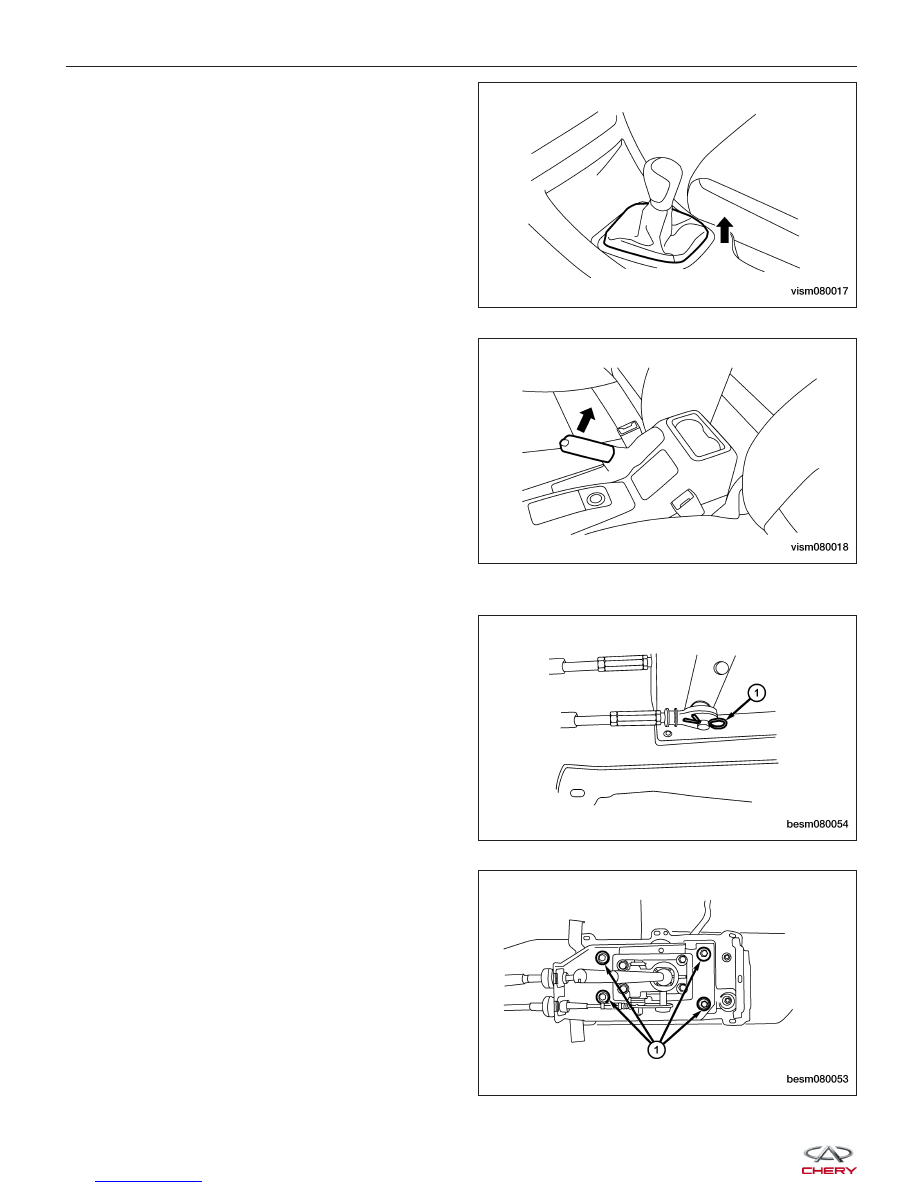
10. Remove the clip on the gearshift mechanism and

then remove the crossover cable and the selector
cable (1) from the gearshift mechanism.

11. Remove the four bolts (1) and then remove the

gearshift mechanism from the bracket.

ON-VEHICLE SERVICE

VISM080017

VISM080018

BESM080054

BESM080053


12. Remove the selector cable clamps (1) and bracket

retaining bolts (2).

13. Remove the gear selector & shifter assembly.

14. Installation is in the reverse order of removal.

NOTE :
Selector cable can be adjusted with the adjusting bolt (1). Adjust bolts as needed to obtain proper cable adjustment.

Disassembly

1. Drive out the locking selector finger (1) pin follow-

ing the direction as shown in the diagram.

2. Drive out the locking pin (2) reverse gear lock

assembly pin.

3. Remove all of the components from shaft.

4. Thoroughly clean and check all parts, replace any

worn parts as necessary.

ON-VEHICLE SERVICE

VISM080006

LTSM080180

LTSM080094

08


Assembly

1. Carefully press and fit two gear shift mechanism

(1) & (2) bearings to the corresponding position on
the gear shift mechanism housing. The bearing (1)
should be pressed to the end, both end faces of
the bearing should align with the hole end faces of
the housing bearing. The side of the bearing with
letters should be placed outwards.

2. Press the air duct into the housing orifice to ensure the air duct is in the proper position.

3. Press and fit the fluid seal of the gearshift shaft into the fluid seal hole of the housing, ensure the fluid seal is

pressed and fitted in position.

NOTE :
Apply transaxle fluid to the fluid lip seal.

4. Install the gearshift shaft through the fluid seal and into the housing of gear shift mechanism.

5. Following the direction of the arrow, install the rear

neutral return spring stop, rear neutral return
spring, reverse gear lock assembly, selector finger
and interlock plate assembly, front neutral return
spring assembly onto the gearshift shaft (as shown
in the figure). Check the turn-down rims of rear
neutral return spring stop, and ensure they have
entered into corresponding vent groove of the
housing. One end of main body of reverse gear
lock with blind hole shall face rear neutral return
spring stop. And the small end face of front neutral
return spring assembly shall face towards selector
finger.

6. Insert the gearshift shaft into the bearing.

7. Install the reverse gear limiter lock mechanism (1)

(as shown in the figure).
(Tighten: Reverse gear limiter bolt to 22 N·m)

8. Install the gearshift fluid seal dust boot to the gearshift shaft fluid seal.

9. Install the gearshift lever assembly to the gearshift shaft, then press it in the pin hole of gearshift lever assembly,

finally install the pin.

NOTE :
Neither end of the pin is allowed to protrude beyond the two end surfaces of the pin holes.

ON-VEHICLE SERVICE

LTSM080138

LTSM080139

LTSM080140


10. Align the selector finger (1) and fork shaft spring

pin (2), install the spring pin of selector finger (as
shown by the arrow in the figure).

11. Tighten the interlock plate limit bolt (1) together

with the shim to the housing (as shown in the fig-
ure). The tightening torque of the bolt is 30 N·m.
Check front end circular cylinder of the bolt to
ensure it is in the corresponding groove of selector
finger.

12. Check the gearshift shaft to ensure it is able to rotate and perform axial movement freely.

13. Install air duct (1) and air duct cap (2). Apply seal-

ant to the surface of the inserted part of air duct.

14. Install the backup light switch assembly (1).

(Tighten: Backup light switch to 32 N·m)

ON-VEHICLE SERVICE

LTSM080094

LTSM080128

LTSM080134

LTSM080135

08


Content   ..  301  302  303  304   ..