Chery Tiggo. Manual - part 302


  Index      Chery     Chery Tiggo - service repair manual 2009 year


Search            


Content   ..  300  301  302  303   ..


Chery Tiggo. Manual - part 302


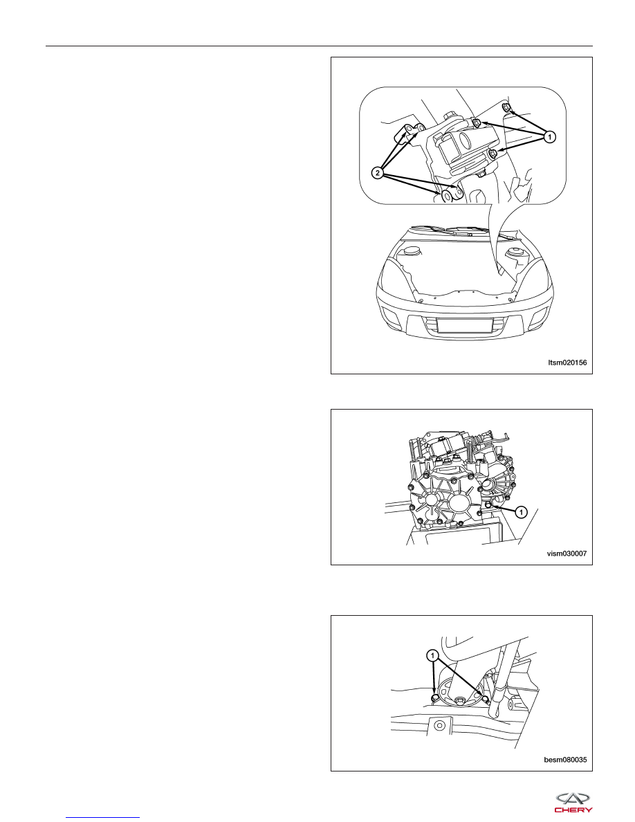
14. Remove transaxle mount nuts (2) and the transaxle

mount bracket bolts (1).
(Tighten: Transaxle mount nuts to 120 N·m)

15. Raise the vehicle.

16. Remove the transaxle drain plug (1) and drain the

transaxle fluid.

17. Remove both front axle shafts (See Front Axle Shaft Removal & Installation in Section 09 Driveline & Axle).

18. Remove the engine undercover and splash shields.

19. Remove the front engine mount bolts (1).

(Tighten: Front mount bolts to 60 N·m)

ON-VEHICLE SERVICE

LTSM020156

VISM030007

BESM080035


20. Remove the rear engine mount bolts (2) and the

rear engine mount bracket bolts (1).
(Tighten: Rear mount bolts to 40 N·m)

21. Remove the sub-frame assembly (See Sub-Frame Assembly Removal & Installation in Section 10 Suspension).

22. Remove the engine to transaxle lower bolts (1).

(Tighten: Transaxle mount bolts to 40 N·m)

23. Separate

the

transaxle

from

the

engine

and

remove it from the vehicle.

WARNING!

Support the transaxle with a suitable jack while removing the transaxle.

24. Installation is in the reverse order of removal.

Installation Notes:
• Refill 2.2L transaxle fluid through the fill hole (1)

until the fluid starts to leak from the fill hole.

• After installation, check for any fluid leakage and

verify the transaxle fluid level is correct.

ON-VEHICLE SERVICE

LTSM020188

VISM080002

LTSM080189

08


Gear Selector & Shifter Assembly

Removal & Installation

ON-VEHICLE SERVICE

LTSM080087


1. Disconnect the negative battery cable.

2. Remove the air cleaner housing assembly.

3. Remove the two shift cables (1) from the transaxle.

4. Remove the shift cable clamp (1) from the shift

cable bracket.

5. Raise and support the vehicle.

1 - Backup Lamp Switch Assembly

2 - Limit Stop Screw-Interlocking Plate

3 - Plain Washer-Interlocking Plate Limit Stop Screw

4 - Bearing-Gear Shift Mechanism

5 - Lower Lining - Selector Lever

6 - Selector Lever Assembly

7 - Washer

8 - Bolt

9 - Upper Dust Boot - Selector Lever

10 - Nut

11 - Plain Washer-Gear Selecting Arm Nu

12 - Gear Shifting Arm Assembly

13 - Gear Shifting Drive Slider

14 - Dust Cap-Gear Shifting Shaft Fluid Seal

15 - Lower Dust Cap-Gear Selecting Arm

16 - Lower Bushing-Gear Selecting Arm

17 - Gear Selecting Arm Assembly

18 - Upper Bushing-Gear Selecting Arm

19 - Baffle-Rear Neutral Position Return Spring

20 - Rear Neutral Retracting Spring

21 - Reverse Gear Lock Assembly

22 - Reverse Gear Lock Assembly Pin

23 - Selector Finger Pin

24 - Selector Finger

25 - Interlock Plate Assembly

26 - Front Neutral Retracting Spring Assembly

27 - Gearshift Shaft

28 - Retainer-Reverse Gear Lock

29 - Gear Shift Mechanism Housing

30 - Air Duct

31 - Air Duct Cap

32 - Bolt

ON-VEHICLE SERVICE

LTSM080087

BESM080051

VISM080026

08


Content   ..  300  301  302  303   ..