Chery Tiggo. Manual - part 248


  Index      Chery     Chery Tiggo - service repair manual 2009 year


Search            


Content   ..  246  247  248  249   ..


Chery Tiggo. Manual - part 248


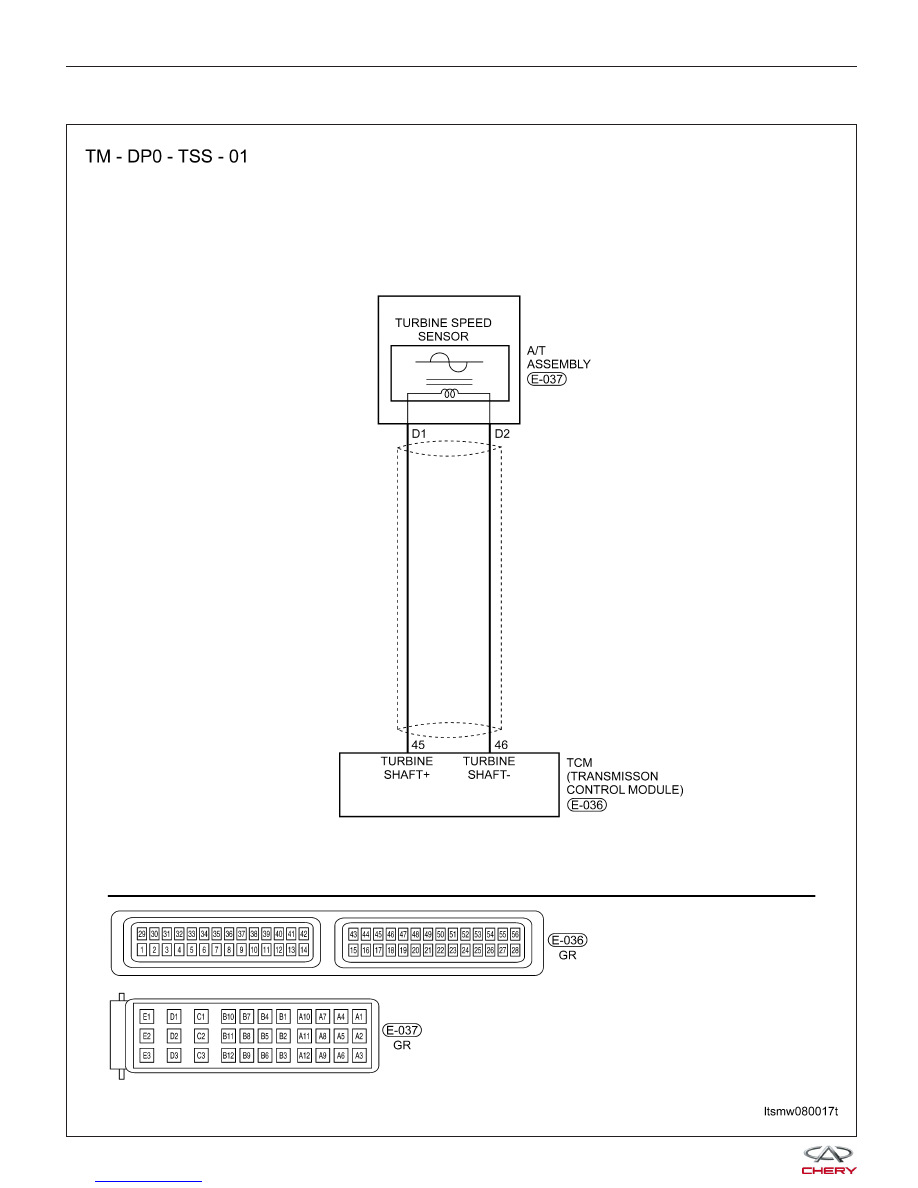
P0715 - Turbine Speed Sensor Affected By Interference

DIAGNOSIS & TESTING

LTSMW080017T


On Board Diagnostic Logic
• Self-diagnosis detection logic.

DTC NO.

DTC DEFINITION

DTC DETECTION

CONDITION

DTC SET

CONDITION

POSSIBLE CAUSES

P0715

Turbine speed

sensor affected by

interference

Engine is running

The Transaxle
Control Module
(TCM) will set this
DTC when the
turbine speed signal
is not present.

• Turbine speed
sensor

• Harness or
connectors (The
sensor circuit is open
or shorted)

• TCM

DTC Confirmation Procedure:

Before performing the following procedure, confirm that battery voltage is more than 12 V.

• Turn ignition switch off.

• Connect the X-431 scan tool to the Data Link Connector (DLC) - use the most current software available.

• Turn ignition switch on.

• With the scan tool, record and erase stored DTCs in the TCM.

• Start engine and warm it to normal operating temperature.

• With the scan tool, select view DTC and data stream.

• If the DTC is detected, the DTC condition is current. Go to Diagnostic Procedure - Step 1.

• If the DTC is not detected, the DTC condition is intermittent (See Diagnostic Help and Intermittent DTC Trou-

bleshooting in Section 08 Transaxle & Transfer Case for more information).

NOTE :
• If using the appropriate diagnostic test tool, you can diagnose the TCM harness while the TCM is still connected.

• Using the appropriate diagnostic test tool in this way will help prevent electrical connector terminal damage.

NOTE :
While performing electrical diagnosis & testing, always refer to the electrical schematics for specific circuit
and component information.

Diagnostic Procedure

1.

CHECK DTC AND TURBINE SPEED SENSOR DATA STREAM

• With the scan tool, select view DTC and data stream for A/T.

• Start the engine.

• Monitor the value of turbine speed sensor while driving.

Is the check result normal and DTC not present?

Yes

>>

The condition that caused this DTC is intermittent (See Diagnostic Help in Section 08 Transaxle &

Transfer Case).

No

>>

Go to the next step.

DIAGNOSIS & TESTING

08


2.

CHECK TURBINE SPEED SENSOR REFERENCE VOLTAGE

• Turn ignition switch on.

• Check reference voltage between A/T assembly terminal D1, D2 and ground.

TURBINE SPEED SENSOR VOLTAGE

A/T ASSEMBLY

CONNECTOR

TERMINAL

GROUND

VOLTAGE

D1

Ground

2 V

D2

• 2 V should exist.

Is 2 V present at each electrical connector pin?

Yes

>>

Go to the next step.

No

>>

Repair or replace the open circuit or short to power or short to ground in harness or connectors.
If circuit is normal, replace the TCM.

3.

CHECK TURBINE SPEED SENSOR RESISTANCE

• Check the resistance of the turbine speed sensor between the turbine speed sensor electrical connector pin D1

and D2, component side.

TURBINE SPEED SENSOR RESISTANCE

TURBINE SPEED SENSOR RESISTANCE

BASED ON TRANSAXLE TEMPERATURE

TERMINAL

RESISTANCE 23°C

D1 - D2

260 - 340

Is the check result normal?

Yes

>>

Go to the next step.

No

>>

Replace the turbine speed sensor.

DIAGNOSIS & TESTING


4.

CHECK DTC

• With the X-431 scan tool, read TCM DTCs.

• Refer to ⬙DTC Confirmation Procedure⬙.

Is DTC P0715 present?

Yes

>>

Replace the TCM.

No

>>

The system is now operating properly.
Reassemble the vehicle and road test to verify the customers complaint is repaired.

DIAGNOSIS & TESTING

08


Content   ..  246  247  248  249   ..