Chery Tiggo. Manual - part 249


  Index      Chery     Chery Tiggo - service repair manual 2009 year


Search            


Content   ..  247  248  249  250   ..


Chery Tiggo. Manual - part 249


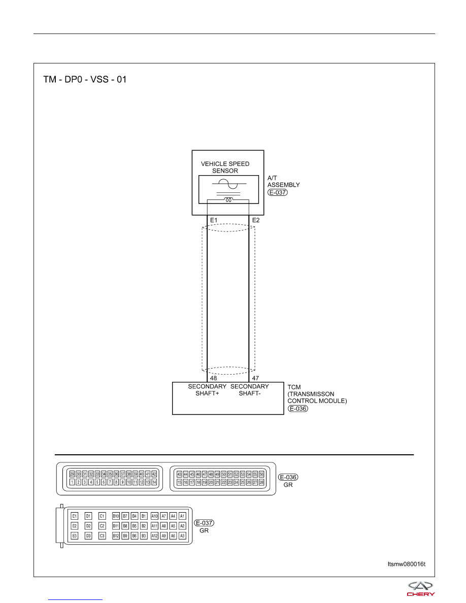
P0730 - Ratio Of Transaxle Error

DIAGNOSIS & TESTING

LTSMW080016T


Operating Components Condition
• Related Operating Components

RELATED OPERATING COMPONENT

GEARSHIFT

LEVER

POSITION

GEAR

RATIO

ENGINE

START

PARKING

MECHANISM

DRIVE

LOCK

2, 3, 4
GEAR

CLUTCH

(E2)

REVERSE

AND 1-3

GEAR

CLUTCH

(E1)

4 GEAR

BRAKE

(F1)

REVERSE

GEAR

BRAKE

(F2)

1, 2

GEAR

BRAKE

(F3)

P

Parking

-

Enabled

-

-

-

-

R

Reverse

Gear

-2.45

-

-

-

-

-

N

Neutral

Gear

-

Enabled

-

-

-

-

-

D

Gear 1

2.75

-

-

-

-

-

Gear 2

1.5

-

-

-

-

-

-

Gear 3

1.000

-

-

-

-

-

-

Gear 4

0.71

-

-

-

-

-

-

公 Operating components

On Board Diagnostic Logic
• Self-diagnosis detection logic.

DTC NO.

DTC DEFINITION

DTC DETECTION

CONDITION

DTC SET

CONDITION

POSSIBLE CAUSE

P0730

Ratio of transaxle

error

Vehicle is driving

The Transaxle
Control Module
(TCM) detects that a
Gear Ratio Error is
already present. The
DTC is set if the
fault happened
within seconds of a
shift.

• Input shaft speed
sensor

• Output shaft speed
sensor

• The retainer of
deceleration clutch

• Transfer case
driven and drive gear

• 2, 3, 4 gear clutch
(E2)

• Reverse and 1 - 3
gear clutch (E1)

• 4 gear brake (F1)

• Reverse gear
brake (F2)

• 1, 2 gear brake
(F3)

• Noise interference

DTC Confirmation Procedure:

Before performing the following procedure, confirm that battery voltage is more than 12 V.

• Connect the X-431 scan tool to the Data Link Connector (DLC) - use the most current software available.

• Turn ignition switch on, with the scan tool, view and erase stored DTCs in the TCM.

• Start the engine and warm it to normal operating temperature.

• With the scan tool, select view DTC and data stream.

• If the DTC is detected, the DTC condition is current. Go to Diagnostic Procedure - Step 1.

• If the DTC is not detected, the DTC condition is intermittent (See Diagnostic Help and Intermittent DTC Trou-

bleshooting in Section 08 Transaxle & Transfer Case for more information).

DIAGNOSIS & TESTING

08


NOTE :
Checking the automatic transaxle fluid quality and fluid level is the most basic check of the automatic transaxle. The
fluid check is also an important inspection to determine if the transaxle will need to be disassembled.

CAUTION:
The burnt scent of ATF fluid indicates that the transaxle fluid is contaminated. The tiny particles in
the fluid pan indicate that the transaxle is worn and it will be necessary to overhaul the transaxle.

NOTE :
While performing electrical diagnosis & testing, always refer to the electrical schematics for specific circuit
and component information.

Diagnostic Procedure

1.

CHECK FLUID QUALITY, FLUID LEVEL AND DTC

• Drive the vehicle until the TFT reaches working temperature (70° - 80°C).

• Park the vehicle on level ground.

• Shift the gear selector lever to all gear positions once, stay in one gear about 5 seconds, then shift to gear

“N”.

• Clean and check the outside of dipstick and remove the dipstick to check the fluid level.

• With the scan tool, select view DTC and data stream for A/T.

• Start the engine.

• Monitor the value of the gear position as indicated in the following table while driving:

SEQUENCE SOLENOID (EVS) CONDITION

LEVER

POSITION

EVS

EVS1

EVS2

EVS3

EVS4

EVS5

EVS6

R

Not

active

Not

active

Not

active

Not

active

Not

active

Not

active

N/P

Not

active

Not

active

Active

Not

active

Not

active

Not

active

1

Not

active

Not

active

Active

Active

Not

active

Not

active

2

Not

active

Active

Not

active

Active

Not

active

Not

active

3

Not

active

Not

active

Not

active

Not

active

Not

active

Not

active

4

Active

Active

Not

active

Not

active

Not

active

Not

active

Is the check result not normal and DTC P0730, DTC P0715 or DTC P0720 present?

Yes

>>

If DTC P0715 is present, see DTC P0715 diagnostic procedure.
If DTC P0720 is present, see DTC P0720 diagnostic procedure.

No

>>

Go to the next step.

DIAGNOSIS & TESTING


2.

HYDRAULIC TEST

• Preheat the transaxle fluid to 80° - 100°C.

• Lift the vehicle until the wheels can rotate freely.
• Connect the special fluid pressure gage onto the

fluid pressure measurement port as (3).

CONNECTOR AND TEST CAVITY

CONNECTOR AND

CAVITY

1

2

3

Figure name

Output speed sensor

Fluid pressure sensor

Fluid pressure test port

STANDARD FLUID PRESSURE TEST

MEASURE STATUS

ENGINE SPEED (RPM)

STANDARD FLUID PRESSURE

(BAR)

Gear lever position

Not running

Below 0.2

D/R

820 RPM

2.6

D/R

1400 RPM

8.7

• In accordance with the shown status of standard fluid pressure measurement table, measure the fluid pressure

of measurement port. The measurement of port should be within the standard range.

• If some measurement values is beyond the standard range, please refer to the fluid pressure measurement and

diagnosis table for causes.

Is the check result normal?

Yes

>>

Go to step 5 for disc or plate abrasion.

No

>>

Go to the next step.

3.

CHECK VALVE BODY ASSEMBLY AND FLUID PUMP AND PIPELINE

• Turn the ignition switch off.

• Remove and disassemble the DP0 Automatic Transaxle Assembly (See Automatic Transaxle Removal & Instal-

lation in Section 08 Transaxle & Transfer Case).

• Check valve body and fluid pump and pipeline.

Is the check result normal?

Yes

>>

Go to the next step.

No

>>

Replace the damaged components as needed.

DIAGNOSIS & TESTING

LTSMD080021

08


Content   ..  247  248  249  250   ..