Chery Tiggo. Manual - part 236


  Index      Chery     Chery Tiggo - service repair manual 2009 year


Search            


Content   ..  234  235  236  237   ..


Chery Tiggo. Manual - part 236


ON-VEHICLE SERVICE

Exhaust Pipe Assembly

Removal & Installation - 1.6L & 1.8L & 2.0L

WARNING!

The normal operating temperature of the exhaust system is very high. Therefore, never work around, or attempt
to service any part of the exhaust system until it has cooled. Special care should be taken when working near
the catalytic converter. The temperature of the converter rises to a high level after a short period of engine oper-
ating time.

1. Raise and support the vehicle.

2. Remove the catalytic converter to exhaust manifold

bolts (1).
(Tighten: Exhaust manifold flange bolts to 49 ± 5
N·m)

3. Remove all the support isolators.

4. Remove the exhaust pipe assembly.

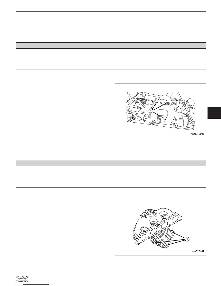
Removal & Installation - 2.4L

WARNING!

The normal operating temperature of the exhaust system is very high. Therefore, never work around, or attempt
to service any part of the exhaust system until it has cooled. Special care should be taken when working near
the catalytic converter. The temperature of the converter rises to a high level after a short period of engine oper-
ating time.

1. Raise and support the vehicle.

2. Remove the catalytic converter to exhaust manifold

bolts (1).
(Tighten: Exhaust manifold flange bolts to 49 ± 5
N·m)

3. Remove all the support isolators.

4. Remove the exhaust pipe assembly.

LTSM070005

LTSM020189

07


Muffler

Removal & Installation

WARNING!

The normal operating temperature of the exhaust system is very high. Therefore, never work around, or attempt
to service any part of the exhaust system until it has cooled. Special care should be taken when working near
the catalytic converter. The temperature of the converter rises to a high level after a short period of engine oper-
ating time.

1. Raise and support the vehicle.

2. Remove the muffler mounting nuts (1).

(Tighten: Muffler mounting nuts to 50 N·m)

3. Remove the support isolators (2).

4. Remove the muffler.

5. Clean the ends of the pipes and the muffler to ensure proper mating of all parts. Discard broken or worn isola-

tors, rusted or overused clamps, supports, and attaching parts.

6. Installation is in the reverse order of removal.

Catalytic Converter

Description

The catalytic converter is attached to the exhaust manifold using fasteners and a gasket for sealing.

The catalytic converter plays a major role in the emission control system. The catalytic converter operates as a gas
reactor. Its catalytic function is to speed the heat-producing chemical reaction of components in the exhaust gases in
order to reduce air pollutants.

Operation

Catalyst operation is dependent on its ability to store and release the oxygen needed to complete the emissions-
reducing chemical reactions. As a catalyst deteriorates, its ability to store oxygen is reduced. Since the catalyst’s
ability to store oxygen is somewhat related to proper operation, oxygen storage can be used as an indicator of cat-
alyst performance.

CAUTION:
Unleaded gasoline must be used in order to avoid damaging the catalyst core.

ON-VEHICLE SERVICE

LTSM070002


Removal & Installation

WARNING!

The normal operating temperature of the exhaust system is very high. Therefore, never work around or attempt
to service any part of the exhaust system until it has cooled. Special care should be taken when working near
the catalytic converter. The temperature of the converter rises to a high level after a short period of engine oper-
ating time.

1. Disconnect the negative battery cable.

2. Raise and support the vehicle.

3. Remove the catalytic converter mounting nuts (1)

and gaskets.
(Tighten: Catalytic converter mounting nuts to 50
N·m)

4. Remove the catalytic converter.

5. Clean the ends of the pipes to ensure proper mat-

ing of all parts. Discard broken or worn isolators,
rusted or overused clamps, supports, and attaching
parts.

6. Installation is in the reverse order of removal.

ON-VEHICLE SERVICE

LTSM070001

07


TRANSAXLE & TRANSFER CASE

08

CONTENTS

page

DP0 Automatic Transaxle . . . . . . . . . . . . . . . . . . . . . . . . . . . . . . . . . . . . . . . . . . . . . . . . . . . . . . . . . . . . . . 08-1

F4A4 Automatic Transaxle . . . . . . . . . . . . . . . . . . . . . . . . . . . . . . . . . . . . . . . . . . . . . . . . . . . . . . . . . . . 08-143

5-Speed Manual Transaxle . . . . . . . . . . . . . . . . . . . . . . . . . . . . . . . . . . . . . . . . . . . . . . . . . . . . . . . . . . . 08-246

Front Differential . . . . . . . . . . . . . . . . . . . . . . . . . . . . . . . . . . . . . . . . . . . . . . . . . . . . . . . . . . . . . . . . . . . 08-307

Clutch System . . . . . . . . . . . . . . . . . . . . . . . . . . . . . . . . . . . . . . . . . . . . . . . . . . . . . . . . . . . . . . . . . . . . . 08-316

Transfer Case (4x4) . . . . . . . . . . . . . . . . . . . . . . . . . . . . . . . . . . . . . . . . . . . . . . . . . . . . . . . . . . . . . . . . . 08-326

DP0 AUTOMATIC TRANSAXLE

GENERAL INFORMATION

08-3

Description

08-3

Operation

08-6

Specifications

08-7

Special Tools

08-8

Electrical Schematics

08-10

DP0 Transaxle Control Module (TCM)
Connector Pin-Out Table

08-18

DIAGNOSIS & TESTING

08-19

Diagnostic Help

08-19

Intermittent DTC Troubleshooting

08-19

Ground Inspection

08-19

Diagnostic Tools

08-19

Diagnostic Trouble Code (DTC) List

08-20

DP0 Automatic Transaxle DTC List

08-20

Diagnostic Trouble Code (DTC) Tests

08-22

P0641 - Sensor Feed

08-22

P0657 - Solenoid Power Supply Circuit
Shorted To Voltage

08-28

P0657 - Solenoid Power Supply Circuit
Open

08-32

P0705 - Multi-Function Switch:
Prohibited Position

08-37

P0710 - Fluid Temperature Sensor

08-42

P0715 - Turbine Speed Sensor Affected
By Interference

08-46

P0730 - Ratio Of Transaxle Error

08-50

P0753 - Shift Solenoid Valve 1 (SSV1)
Open Circuit Or Short To Power Supply
Or Short To Ground

08-56

P0758 - Shift Solenoid Valve 2 (SSV2)
Open Circuit Or Short To Power Supply
Or Short To Ground

08-62

P0763 - Shift Solenoid Valve 3 (SSV3)
Short To Power Supply, P0763 - Shift
Solenoid Valve 3 (SSV3) Open Or
Short To Ground Circuit

08-68

P0768 - Shift Solenoid Valve 4 (SSV4)
Short To Power Supply, P0768 - Shift
Solenoid Valve 4 (SSV4) Open Or
Short To Ground Circuit

08-74

P0773 - Shift Solenoid Valve 5 (SSV5)
Short To Power Supply, P0773 - Shift
Solenoid Valve 5 (SSV5) Open Or
Short To Ground Circuit

08-81

P0775 - EVM (Modulation Solenoid
Valve) Open Circuit Or Short To
Ground, P0775 - EVM (Modulation
Solenoid Valve) Shorted To Voltage

08-87

P0795 - Torque Converter Lock
Solenoid Valve (EVLU) Open Circuit Or
Short To Ground, P0795 - Torque
Converter Lock Solenoid Valve (EVLU)
Short To Voltage

08-93

P0840 - Pressure Sensor

08-99

P1928 - Shift Lock Solenoid Valve
Circuit Shorted To Voltage

08-104

P1928 - Shift Lock Solenoid Valve
Open Circuit Or Short To Ground

08-109

P2709 - Shift Solenoid Valve 6 (SSV6)
Short To Power Supply

08-114

P2709 - Shift Solenoid Valve 6 (SSV6)
Open Circuit Or Short To Ground

08-119

08


Content   ..  234  235  236  237   ..