Chery Tiggo. Manual - part 230


  Index      Chery     Chery Tiggo - service repair manual 2009 year


Search            


Content   ..  228  229  230  231   ..


Chery Tiggo. Manual - part 230


GENERAL INFORMATION

Description

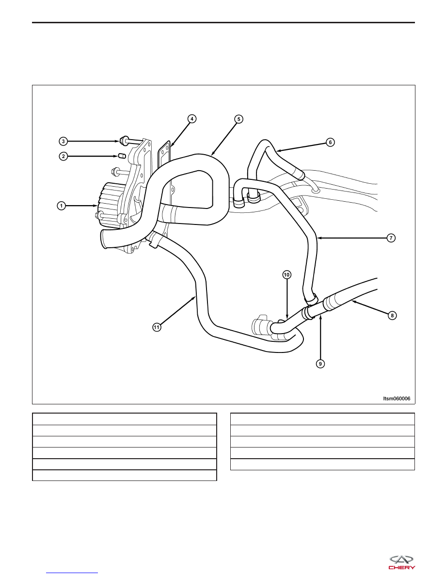
Water Pump Assembly - 1.6L & 1.8L & 2.0L

1 - Water Pump Assembly

2 - Water Pump Alignment Pin

3 - Water Pump Bolt

4 - Gasket

5 - Engine Inlet Hose From Radiator

6 - Restrictor Outlet Hose

7 - Restrictor Inlet Hose

8 - Engine Oil Cooler Inlet Hose (Part 1)

9 - Three Way Connector

10 - Engine Oil Cooler Inlet Hose (Part 2)

11 - Engine Oil Cooler Outlet Hose

LTSM060006


The cooling system regulates engine operating temperature. It allows the engine to reach normal operating temper-
ature as soon as possible, maintains normal operating temperature and prevents overheating.

The cooling system also provides a means of heating the passenger compartment. The cooling system is pressurized
and uses a centrifugal water pump to circulate coolant throughout the system.

The cooling system consists of the following components:

• Radiator

• Coolant

• Coolant pump

• Electric cooling fans

• Electric cooling fans control module

• Thermostat

• Coolant reservoir

Thermostat Housing Assembly - 1.6L & 1.8L & 2.0L

1 - Gasket

2 - Coolant Temperature Sensor

3 - Thermostat Housing Assembly

4 - Thermostat Housing Mounting Bolts

5 - Minor Cycle Water Hose

6 - Thermostat Housing Cover

7 - Thermostat Housing Cover Mounting Bolts

8 - Thermostat Assembly

GENERAL INFORMATION

LTSM060007

06


• Hoses and clamps

• Coolant temperature sensor

• Coolant temperature sensor (for instrument cluster) (with 2.4L engine)

• Heater core

Operation

The primary purpose of a cooling system is to maintain engine temperature in a range that will provide satisfactory
engine performance and emission levels under all expected driving conditions. It also provides hot coolant for heater
performance and cooling for automatic transmission oil. This is done by transferring heat from engine metal to cool-
ant, moving the heated coolant to the radiator, and then transferring the heat to the ambient air.

Engine Coolant Flow Diagram - 1.6L & 1.8L & 2.0L

1 - To Heater Core

2 - Heater Core Return

3 - To Oil Cooler

4 - Oil Cooler Return

5 - To Restrictor

6 - To Engine

7 - Radiator Return

8 - Restrictor Return

9 - Minor Cycle Coolant Hose

10 - To Radiator

GENERAL INFORMATION

LTSM060005


Specifications

Torque Specifications

DESCRIPTION

TORQUE (N·m)

Coolant Pump Mounting Bolts

14

Radiator Support Mounting Bolts

5

Coolant Fan Mounting Bolts

5

Thermostat Mounting Bolts

13

Fluid Specifications

DESCRIPTION

CAPACITY (L)

Cooling System

7.0

Special Tools

Cooling System Pressure Tester

GENERAL INFORMATION

06


Content   ..  228  229  230  231   ..