Chery Tiggo. Manual - part 190
4.
CHECK THE O
2
SENSOR GROUND CIRCUIT FOR AN OPEN OR SHORT
• Disconnect ECM harness connector.
• Check harness continuity between upstream O
2
sensor terminal 1 in connector E-074 and ECM terminal 76 in
connector E-054.
• Check harness continuity between downstream O
2
sensor terminal 1 in connector B-011 and ground.
• Continuity should exist.
• Check harness for a short to power and short to ground.
Is the check result normal?
Yes
>>
Go to the next step.
No
>>
Repair the circuits for an open or short to power or short to ground in harness or connectors.
5.
CHECK THE O
2
SENSOR INPUT SIGNAL CIRCUIT FOR AN OPEN OR SHORT
• Check harness continuity between ECM terminal and O
2
sensor terminal as follows.
• Continuity should exist.
• Check harness continuity between following terminals and ground.
• Continuity should not exist.
COMPONENT
ECM TERMINAL
O
2
SENSOR TERMINAL
Upstream O
2
sensor
60
4
Downstream O
2
sensor
59
4
• Also Check harness short to power supply circuit.
Is the check result normal?
Yes
>>
Go to the next step.
No
>>
Repair circuit for an open or short to power or short to ground in harness or connectors.
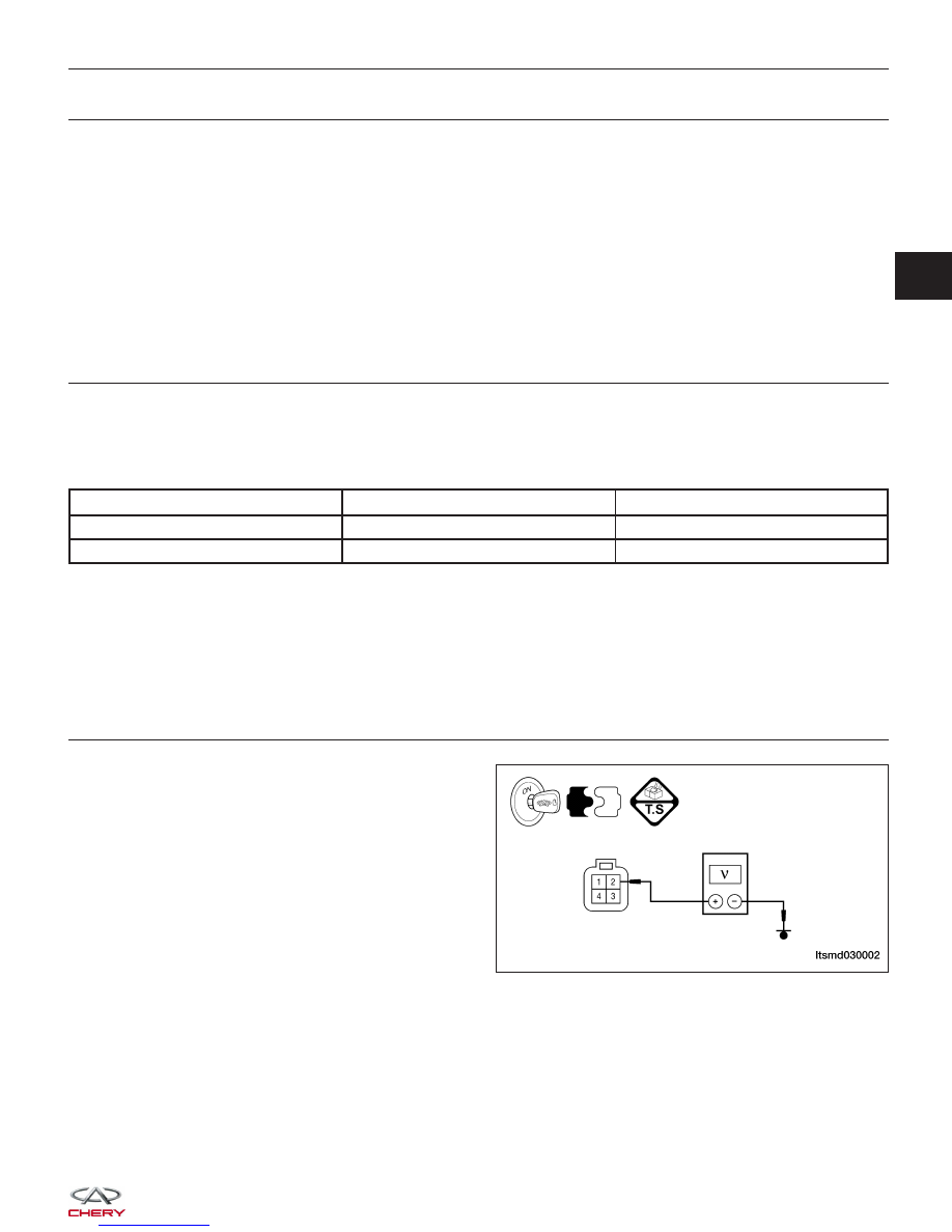
6.
CHECK O
2
SENSOR POWER SUPPLY
• Turn ignition switch on.
• Check power supply between O
2
sensor E-074, ter-
minal 2 and ground.
• Battery voltage should exist.
Is the check result normal?
Yes
>>
Go to step 8.
No
>>
Go to the next step.
DIAGNOSIS & TESTING
LTSMD030002
03