Chery Tiggo. Manual - part 188


  Index      Chery     Chery Tiggo - service repair manual 2009 year


Search            


Content   ..  186  187  188  189   ..


Chery Tiggo. Manual - part 188


Specification data are reference values and are measured between each terminal and ground.

TERMINAL NO.

ITEM

CONDITION

DATA (DC VOLTAGE)

13

ECM ground

Ignition switch: ON

Approximately 0 V

26

ECM ground

Ignition switch: ON

Approximately 0 V

Confirmation Procedure:

Before performing the following procedure, confirm that battery voltage is more than 12 V.

• Turn ignition switch off.

• Connect the X-431 scan tool to the Data Link Connector (DLC) - use the most current software available.

• Start the engine and warm it to normal operating temperature.

• With the scan tool, select view data stream.

• If the data stream is not detected, the condition is current. Go to Diagnostic Procedure Step 1.

• If the data stream is detected, the condition is intermittent (See Diagnosis & Testing Diagnostic Help in Section

03 Electronic Engine Controls).

NOTE :
While performing electrical diagnosis & testing, always refer to the electrical schematics for specific circuit
and component information.

Diagnostic Procedure

1.

INSPECTION START

• Start engine.

Is engine running?

Yes

>>

Go to step 8.

No

>>

Go to step 2.

2.

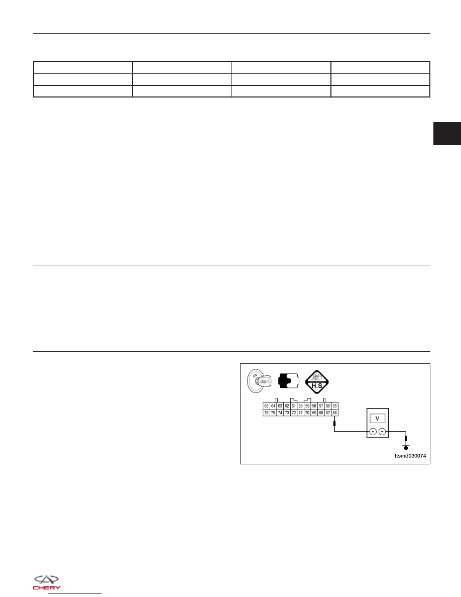
CHECK ECM POWER SUPPLY CIRCUIT - (1)

• Turn ignition switch OFF and then ON position.

• Check voltage between ECM terminal 66 and

ground.

• Battery voltage should exist.

Is the check result normal?

Yes

>>

Go to step 5.

No

>>

Go to step 3.

DIAGNOSIS & TESTING

LTSMD030074

03


3.

DETECT MALFUNCTIONING PART

• Check the following:

− Fuse 17
− Harness connectors C-103, E-103, terminal 1
− Front fuse and relay box connector A
− Harness open or short between ECM and fuse

Is the check result normal?

Yes

>>

Go to the next step.

No

>>

Repair or replace malfunctioning parts.

4.

CHECK ECM POWER SUPPLY CIRCUIT - (2)

• Check voltage between ECM terminal 64 and ground.

• Battery voltage should exist.

Is the check result normal?

Yes

>>

Go to the next step.

No

>>

Check the following:

Harness connectors A-102, E-105, terminal 4

Front fuse and relay box connector A

Harness open or short between ECM and battery

5.

CHECK GROUND CONNECTIONS

• Turn ignition switch off.

• Loosen and retighten ground screws on the body.

Is the check result normal?

Yes

>>

Go to the next step.

No

>>

Repair or replace ground connections.

6.

CHECK ECM GROUND CIRCUIT FOR AN OPEN OR SHORT

• Disconnect ECM harness connector.

• Check harness continuity between ECM terminals 13, 26 and ground.

• Continuity should exist.

• Also check harness for short to power.

Is the check result normal?

Yes

>>

Go to step 8.

No

>>

Go to the next step.

7.

DETECT MALFUNCTIONING PART

• Check harness for open or short between ECM terminals 13, 26 and ground.

• Repair open circuit or short to power in harness or connectors.

Is the check result normal?

Yes

>>

Go to the next step.

No

>>

Repair circuit for an open or short to power in harness or connectors.

DIAGNOSIS & TESTING


8.

CHECK ECM POWER SUPPLY CIRCUIT - (3)

•  Turn ignition switch on and then off.

•  Check voltage between ECM terminals 12, 25 and ground.

•  Voltage: Turn ignition switch on battery voltage will be exist and after turning ignition switch off, battery voltage

 will exist a few seconds, then drop to approximately 0 V.

Is the check result normal?

Yes

>>

Check the starting system.

No

>>

Go to the next step.

9.

CHECK STARTER RELAY SUPPLY VOLTAGE

•  Turn ignition switch off. Wait for at least 10 seconds.

•  Check voltage between ECM terminal 34 and ground.

• Battery voltage should exist.

Is the check result normal?

Yes

>>

Go to the next step.

No

>>

Go to step 11.

10.

CHECK ECM POWER SUPPLY CIRCUIT - (4)

•  Disconnect ECM harness connector.

•  Disconnect front fuse and relay box harness connector F.

•  Check harness continuity between ECM terminals 12, 25 and front fuse and relay box terminal F3.

•  Continuity should exist.

•  Also check harness for short to ground and short to power.

Is the check result normal?

Yes

>>

Go to step 12.

No

>>

Repair circuit for an open or short in harness or connectors.

11.

CHECK STARTER RELAY CIRCUIT

•  Disconnect ECM harness connector.

•  Disconnect front fuse and relay box harness connector A, G.

•  Check harness continuity between ECM terminal 34 and front fuse and relay box terminal A1.

•  Check harness continuity between front fuse and relay box terminal A1 and G5,

•  Check harness continuity between front fuse and relay box terminal A13 and G5,

•  Continuity should exist.

•  Also check harness for short to ground and short to power.

Is the check result normal?

Yes

>>

Go to the next step.

No

>>

Repair circuit for an open or short to ground or short to power in harness or connectors.

DIAGNOSIS & TESTING

03


12.

CHECK FUSE

• Disconnect fuse 12 (30A), fuse 24 (5A), fuse 25 (10A), front fuse and relay box.

• Check fuse.

Is the check result normal?

Yes

>>

Go to the next step.

No

>>

Replace fuse 12, 23, 24.

13.

CHECK FRONT FUSE AND RELAY BOX

• Check front fuse and relay box.

• Check harness continuity between front fuse and relay box and battery.

Is the check result normal?

Yes

>>

Replace the ECM.

No

>>

Replace or repair front fuse and relay box or harness.

DIAGNOSIS & TESTING


Content   ..  186  187  188  189   ..