Chery Tiggo. Manual - part 178
6.
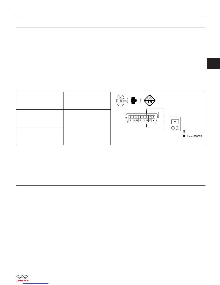
CHECK CAN-BUS LINE
• Connect battery positive cable.
• Connect TCM and ECM connectors (See Transaxle Control Module Remove & Installation in Section 08 Trans-
axle).
• Turn ignition switch on.
• Check CAN-Bus voltage between following terminals.
CAN-H
− 0.025 V should exist while not activate communication.
− 0.65 V should exist while activate communication.
CAN-L
− 11 V should exist while not activate communication.
− 4.65 V should exist while activate communication.
DLC TERMINAL
GROUND
6 (CAN-H)
Ground
14 (CAN-L)
Is the check result normal and DTC U0001 not present?
Yes
>>
Replace the CAN converter.
The problem caused by the CAN converter internal error.
No
>>
Go to the next step.
7.
CHECK CAN-BUS LINE
• Turn ignition switch off.
• Connect CAN converter.
• Disconnect TCM connectors (See Transaxle Control Module Remove & Installation in Section 08 Transaxle).
• Turn ignition switch on.
• Check CAN-Bus voltage as the standard value.
Is the check result normal and DTC U0001 not present?
Yes
>>
Replace TCM.
The problem caused by TCM internal error.
No
>>
Go to the next step.
DIAGNOSIS & TESTING
03