Chery Tiggo. Manual - part 179


  Index      Chery     Chery Tiggo - service repair manual 2009 year


Search            


Content   ..  177  178  179  180   ..


Chery Tiggo. Manual - part 179


Upstream Oxygen Sensor

The input from the upstream heated oxygen sensor tells the Engine Control Module (ECM) the oxygen content of the
exhaust gas. Based on this input, the ECM fine tunes the air-fuel ratio by adjusting injector pulse width.

Downstream Oxygen Sensor

The downstream heated oxygen sensor signal is used to detect catalytic convertor deterioration. As the convertor
deteriorates, the signal from the downstream sensor begins to match the upstream sensor signal except for a slight
time delay. By comparing the downstream heated oxygen sensor signal to the signal from the upstream sensor, the
ECM calculates catalytic convertor efficiency. This calculation is also used to establish the upstream O2 goal voltage
(switching point).

Removal & Installation - Upstream Oxygen Sensor

1. Disconnect the negative battery cable.

2. Disconnect the oxygen sensor electrical connector.

CAUTION:
Remove the oxygen sensor after the exhaust pipe has cooled.

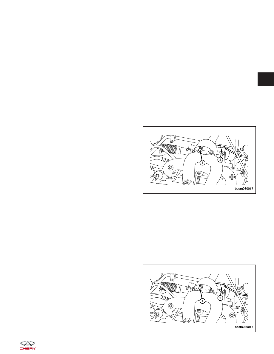
3. Remove the upstream oxygen sensor (1).

(Tighten: Upstream oxygen sensor to 45 N·m)

4. Installation is in the reverse order of removal.

Installation Notes:
• Before installing the oxygen sensor, coat the threads with rust inhibiting lubricant.

Removal & Installation - Downstream Oxygen Sensor

1. Disconnect the negative battery cable.

2. Disconnect the oxygen sensor electrical connector.

CAUTION:
Remove the oxygen sensor after the exhaust pipe has cooled.

3. Remove the downstream oxygen sensor (2).

(Tighten: Downstream oxygen sensor to 45 N·m)

ON-VEHICLE SERVICE

BESM030017

BESM030017

03


4. Installation is in the reverse order of removal.

Installation Notes:
• Before installing the oxygen sensor, coat the threads with rust inhibiting lubricant.

Crankshaft Position (CKP) Sensor

Description

The Crankshaft Position (CKP) sensor is located on the flywheel shell facing the gear teeth of the signal plate. It
detects the fluctuation of the engine revolution. The sensor consists of a permanent magnet and Induction coil.

Operation

When the engine is running, the high and low parts of the teeth cause the gap with the sensor to change. The
changing gap causes the magnetic field near the sensor to change. Due to the changing magnetic field, the voltage
from the sensor changes. The Engine Control Module (ECM) receives the voltage signal and detects the fluctuation
of the engine revolution.

Removal & Installation

1. Disconnect and isolate the negative battery cable.

2. Disconnect the CKP sensor electrical connector.

3. Remove the CKP sensor retaining bolt (1) and

remove the CKP sensor.
(Tighten: Crankshaft position sensor retaining bolt
to 10 N·m)

4. Installation is in the reverse order of removal.

ON-VEHICLE SERVICE

LTSM030036


Camshaft Position (CMP) Sensor

Description

The Camshaft Position (CMP) sensor senses the protrusion of inlet valve cam sprocket to identify a particular cyl-
inder. The CMP sensor senses the piston position. When the Crankshaft Position (CKP) sensor becomes inoperative,
the CMP sensor provides various controls of engine parts instead, utilizing timing of cylinder identification signals.
The sensor consists of a permanent magnet and Hall IC.

Operation

When engine is running, the high and low parts of the teeth cause the gap with the sensor to change. The changing
gap causes the magnetic field near the sensor to change. Due to the changing magnetic field, the voltage from the
sensor changes. The Engine Control Module (ECM) detects the voltage signal and identify piston position and cyl-
inder timing.

Removal & Installation

1. Disconnect the negative battery cable.

2. Disconnect the CMP sensor electrical connector.

3. Remove the CMP sensor retaining bolt (1).

(Tighten: Camshaft position sensor retaining bolt to
7 N·m)

4. Remove CMP sensor.

5. Pull sensor up out of the cylinder head cover.

6. Installation is in the reverse order of removal.

Air Flow Sensor

Description

The air flow sensor is placed in the air intake hose. The air flow sensor measures the intake flow rate by measuring
a part of the entire intake flow. The air flow sensor converts the amount of air drawn into the engine into a voltage
signal. The Engine Control Module (ECM) needs to know intake air volume to calculate engine load. This is neces-
sary to determine how much fuel to inject.

Operation

The air flow sensor controls the temperature of the hot wire to a certain amount. The heat generated by the hot wire
is reduced as the intake air flows around it. The more air, the greater the heat loss. Therefore, the electric current
supplied to the hot wire is changed to maintain the temperature of the hot wire as air flow increases. The ECM
detects the air flow by means of this voltage signal change.

Removal & Installation

1. Disconnect the negative battery cable.

2. Remove the engine cover.

3. Disconnect the air flow sensor electrical connector.

ON-VEHICLE SERVICE

BESM030016

03


4. Remove the air flow sensor retaining bolts (1).

(Tighten: Air flow sensor retaining bolts to 5 N·m)

5. Pull sensor up and take out of the air cleaner case.

6. Installation is in the reverse order of removal.

Accelerator Sensor

Description

The accelerator sensor is located on the right front crossbeam.

Operation

The accelerator sensor monitors the road conditions. It sends a signal to the ECM, the ECM determines if a possible
misfire condition exists.

Removal & Installation

1. Disconnect the negative battery cable.

2. Disconnect the accelerator sensor connect.

3. Remove the accelerator sensor (1).

4. Installation is in the reverse order of removal.

Speed Control System

Description

The Speed Control System allows a driver to keep the vehicle at a predetermined speed without depressing the
accelerator pedal. The driver can set vehicle speed in advance between approximately 25 km/h and 130 km/h.

ECM controls throttle angle of electronic throttle control actuator to regulate engine speed.

If any malfunction occurs in the Speed Control System, it automatically deactivates the system and the cruise indi-
cator flashes.

ON-VEHICLE SERVICE

BESM030029

LTSM030030


Content   ..  177  178  179  180   ..