Chery Tiggo. Manual - part 176
4.
DETECT MALFUNCTIONING PART
• Check the following:
− Harness connectors E-102, C-102
− Harness open and short between APP sensor 1 and ECM
Is the check result normal?
Yes
>>
Replace the ECM.
NOTE : The Immobilizer control module must be matched to the new ECM (See ECM Removal & Instal-
lation in Section 03 Electronic Engine Controls).
No
>>
Repair or replace malfunctioning part.
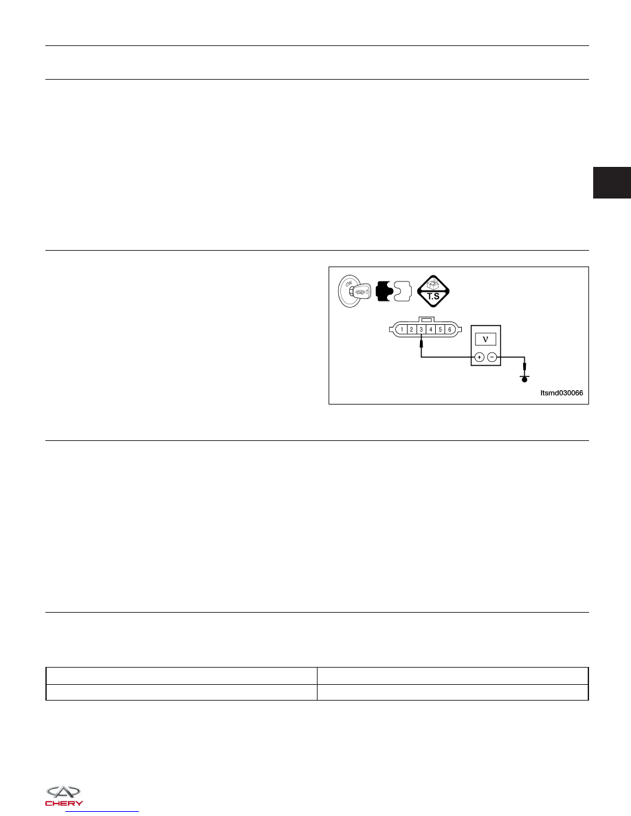
5.
CHECK APP SENSOR 2 POWER SUPPLY CIRCUIT
• Check APP sensor supply voltage between sensor
terminal 3 and ground in the sensor electrical con-
nector C-009.
• Approximately 5 V should exist.
Is the check result normal?
Yes
>>
Go to step 7.
No
>>
Go to the next step.
6.
DETECT MALFUNCTIONING PART
• Check the following:
− Harness connectors E-102, C-102
− Harness open and short between APP sensor 2 and ECM
Is the check result normal?
Yes
>>
Replace the ECM.
NOTE : The Immobilizer control module must be matched to the new ECM (See ECM Removal & Instal-
lation in Section 03 Electronic Engine Controls).
No
>>
Repair or replace malfunctioning part.
7.
CHECK TPS POWER SUPPLY CIRCUIT
• Check harness for short to power and short to ground, between following terminals.
Check TPS Power Supply
ECM TERMINAL
TPS TERMINAL
32
3
Is the check result normal?
Yes
>>
Go to the next step.
No
>>
Repair circuit for a short to ground or short to power in harness or connectors.
DIAGNOSIS & TESTING
LTSMD030066
03