Chery Tiggo. Manual - part 169


  Index      Chery     Chery Tiggo - service repair manual 2009 year


Search            


Content   ..  167  168  169  170   ..


Chery Tiggo. Manual - part 169


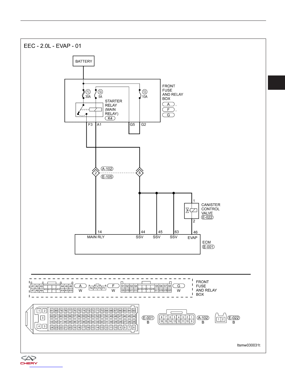
P0444 - Evaporative Emission System Purge Control Valve Circuit Open

DIAGNOSIS & TESTING

LTSMW030031T

03


Check reference values between ECM terminals and ground under the following conditions:

ECM TERMINAL NO.

ITEM

CONDITION

X-431 DATA STREAM

46

Canister control valve

Engine is running

0 % - 99.9 %

On Board Diagnostic Logic
• Self-diagnosis detection logic.

DTC NO.

DTC DEFINITION

DTC DETECTION

CONDITION

DTC SET

CONDITION

POSSIBLE CAUSE

P0444

Evaporative

emission system

purge control valve

circuit open

Engine is running

ECM detected that
the improper voltage
signal is sent to
ECM.

• EVAP canister
control valve

• Harness or
connectors

• ECM

DTC Confirmation Procedure:

Before performing the following procedure, confirm that battery voltage is more than 12 V.

• Turn ignition switch off.

• Connect the X-431 scan tool to the Data Link Connector (DLC) - use the most current software available.

• Turn ignition switch on.

• With the scan tool, record and erase stored DTCs in the ECM.

• Start engine and warm it up to the normal operating temperature then select view DTC.

• If DTC is detected, go to Diagnostic Procedure - Step 1.

• If the DTC is not detected, the DTC condition is intermittent (See Diagnosis & Testing Diagnostic Help in Sec-

tion 03 Electronic Engine Controls).

NOTE :
While performing electrical diagnosis & testing, always refer to the electrical schematics for specific circuit
and component information.

Diagnostic Procedure

1.

CHECK GROUND CONNECTIONS

• Turn ignition switch off.

• Loosen and retighten ground screws on the body (See Ground Inspection in Section 03 Electronic Engine Con-

trols).

• Inspect ground connections E-207 and E-208 mounting position (See Vehicle Wiring Harness Layout - Engine

Room Harness (With 2.0L Engine) in Section 16 Wiring).

Are the ground connections OK?

Yes

>>

Go to the next step.

No

>>

Repair or replace ground harness or connections.

DIAGNOSIS & TESTING


2.

CHECK EVAP CANISTER CONTROL VALVE ACTION

• Start engine and warm it up to the normal operating temperature then select view DTC.

• Touch the EVAP canister valve body, raise engine speed up to 2,000 RPM.

• If the scan tool X-431 with the ⬙ACTIVE TEST⬙ function of the EVAP canister valve, touch the EVAP canister

valve body, perform the action test.

• Slight vibration and concussion should exist.

Is the check result normal?

Yes

>>

Go to step 8.

No

>>

Go to the next step.

3.

CHECK THE EVAP CANISTER CONTROL VALVE ELECTRICAL CONNECTOR

• Turn ignition switch off.

• Disconnect the EVAP canister control valve (1)

electrical connector.

• Inspect the electrical connector for damage.

Is the electrical connector OK?

Yes

>>

Go to the next step.

No

>>

Repair or replace the electrical connector

as necessary.

4.

CHECK EVAP CANISTER CONTROL VALVE POWER SUPPLY CIRCUIT

• Turn ignition switch on.

• Check supply voltage between EVAP canister con-

trol valve terminal 1 and ground.

• 12 V should exist.

Is the check result normal?

Yes

>>

Go to step 7.

No

>>

Go to the next step.

DIAGNOSIS & TESTING

VISMD030007

LTSMD030046

03


5.

DETECT MALFUNCTIONING PART

• Check the following:

− Harness connectors A-102, E-105
− Front fuse and relay box
− Fuse 23, fuse 24, fuse 12
− Harness between EVAP canister control valve and fuse

Is the check result normal?

Yes

>>

Go to the next step.

No

>>

Repair or replace malfunctioning part.

6.

CHECK EVAP CANISTER CONTROL VALVE CONTROL CIRCUIT FOR AN OPEN

• Check voltage between EVAP canister control valve terminal 2 and ground.

• Approximately 3.6 V should exist.

Is the check result normal?

Yes

>>

Go to the next step.

No

>>

Repair or replace circuit for an open in harness or connectors.
If harness is normal, go to the next step.

7.

CHECK EVAP CANISTER CONTROL VALVE

• Turn ignition switch off.

• Remove EVAP canister control valve.

• Check resistance between EVAP canister terminal 1 and 2 as shown in table.

EVAP CANISTER

CONTROL VALVE

TERMINAL NO.

RESISTANCE

⍀ (20°C)

1 - 2

Approximately 26

• Check air passage continuity and operation when apply 12 V current supply voltage between terminal 1 and 2.

• The check results should match specification.

Is the check result normal?

Yes

>>

Go to the next step.

No

>>

Repair or replace EVAP canister control valve.

DIAGNOSIS & TESTING


Content   ..  167  168  169  170   ..