Chery Tiggo. Manual - part 167


  Index      Chery     Chery Tiggo - service repair manual 2009 year


Search            


Content   ..  165  166  167  168   ..


Chery Tiggo. Manual - part 167


• continuity should exist.

• Also check harness for short to ground and short to power.

Is the check result normal?

Yes

>>

Go to step 5.

No

>>

Repair circuit for an open or short in harness or connectors.

5.

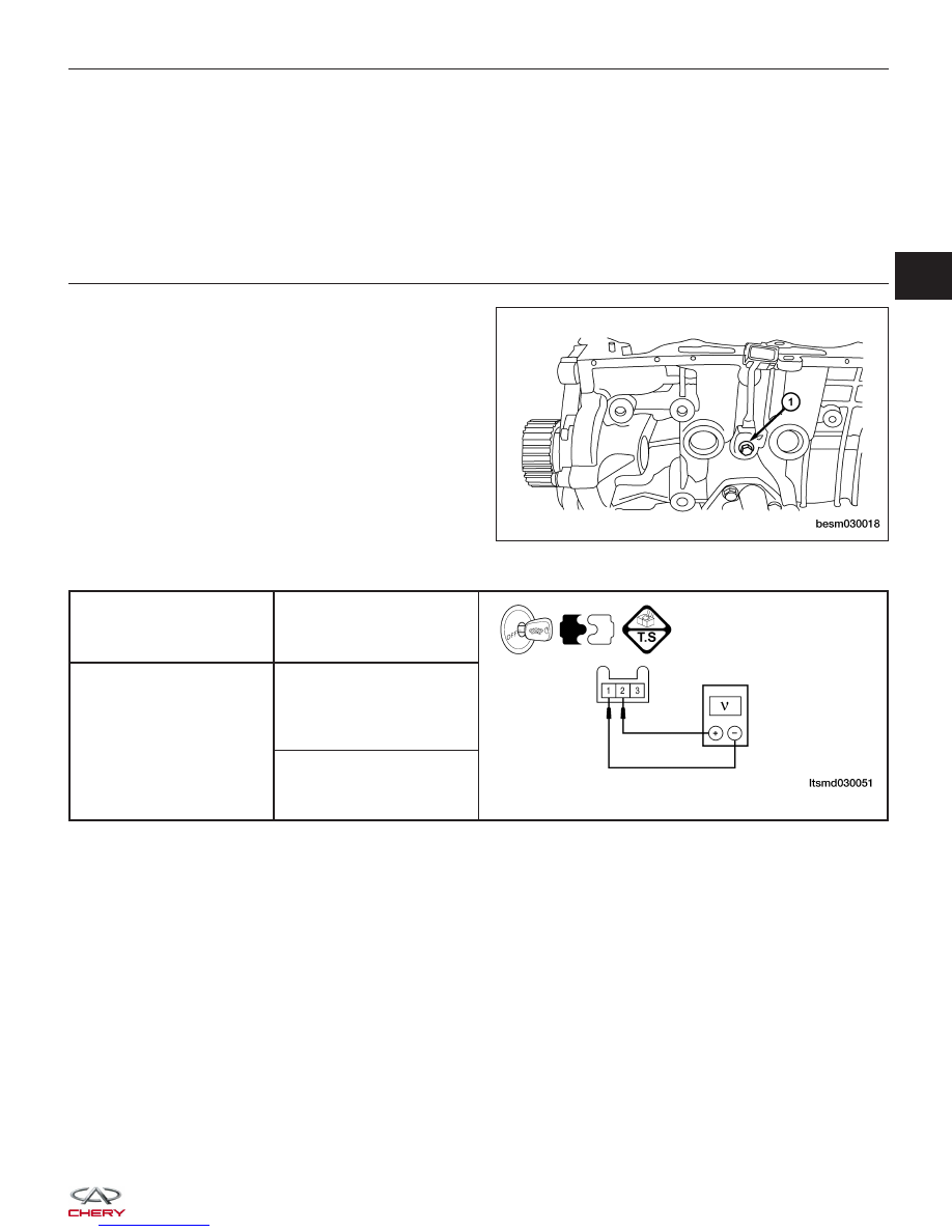
CHECK KNOCK SENSOR SIGNAL

• Connect knock sensor connector.

• Check knock sensor (1) output signal as table

shown.

• Set digital multimeter to the voltage range.

KNOCK SENSOR

TERMINAL NO.

TEST METHOD

1 & 2

Test Method 1: Knock at

cylinder with rubber

hammer

Test Method 2: Knock at

sensor slightly

• Output signal voltage should exist.

Is the check result normal?

Yes

>>

Go to the next step.

No

>>

Replace knock sensor.

DIAGNOSIS & TESTING

BESM030018

03


6.

CHECK DTC

• With the X-431 scan tool, read ECM DTCs.

• Refer to ⬙DTC Confirmation Procedure⬙.

Is DTC P0324 still present?

Yes

>>

Replace the ECM.

NOTE : The Immobilizer control module must be matched to the new ECM (See ECM Removal & Instal-

lation in Section 03 Electronic Engine Controls).

No

>>

The system is now operating properly.
Reassemble the vehicle and road test to verify the customers complaint is repaired.

DIAGNOSIS & TESTING


P0343 - Camshaft Position Sensor Circuit High Input

DIAGNOSIS & TESTING

LTSMW030032T

03


Check reference values between ECM terminals and ground under the following conditions:

ECM TERMINAL NO.

ITEM

CONDITION

DATA (AVERAGE DC

VOLTAGE)

79

Camshaft Position (CMP)

sensor

• Ignition switch: ON

• Engine: Not cranking

11 V

On Board Diagnostic Logic
• Self-diagnosis detection logic.

DTC NO.

DTC DEFINITION

DTC DETECTION

CONDITION

DTC SET

CONDITION

POSSIBLE CAUSE

P0343

Camshaft Position

(CMP) sensor circuit

high input

Engine is running

ECM detected that

the input signal is

out of the

acceptable range.

• CMP sensor

• Camshaft

• Harness or
connectors

• ECM

DTC Confirmation Procedure:

Before performing the following procedure, confirm that battery voltage is more than 12 V.

• Turn ignition switch off.

• Connect the X-431 scan tool to the Data Link Connector (DLC) - use the most current software available.

• Turn ignition switch on.

• With the scan tool, record and erase stored DTCs in the ECM.

• Run engine for a while then select view DTC.

• If DTC is detected, go to Diagnostic Procedure - Step 1.

• If the DTC is not detected, the DTC condition is intermittent (See Diagnosis & Testing Diagnostic Help in Sec-

tion 03 Electronic Engine Controls).

NOTE :
While performing electrical diagnosis & testing, always refer to the electrical schematics for specific circuit
and component information.

Diagnostic Procedure

1.

CHECK GROUND CONNECTIONS

• Turn ignition switch off.

• Loosen and retighten ground screws on the body (See Ground Inspection in Section 03 Electronic Engine Con-

trols).

• Inspect ground connections E-207 and E-208 mounting position (See Vehicle Wiring Harness Layout - Engine

Room Harness (With 2.0L Engine) in Section 16 Wiring).

Are the ground connections OK?

Yes

>>

Go to the next step.

No

>>

Repair or replace ground harness or connections.

DIAGNOSIS & TESTING


Content   ..  165  166  167  168   ..