Chery Tiggo. Manual - part 165


  Index      Chery     Chery Tiggo - service repair manual 2009 year


Search            


Content   ..  163  164  165  166   ..


Chery Tiggo. Manual - part 165


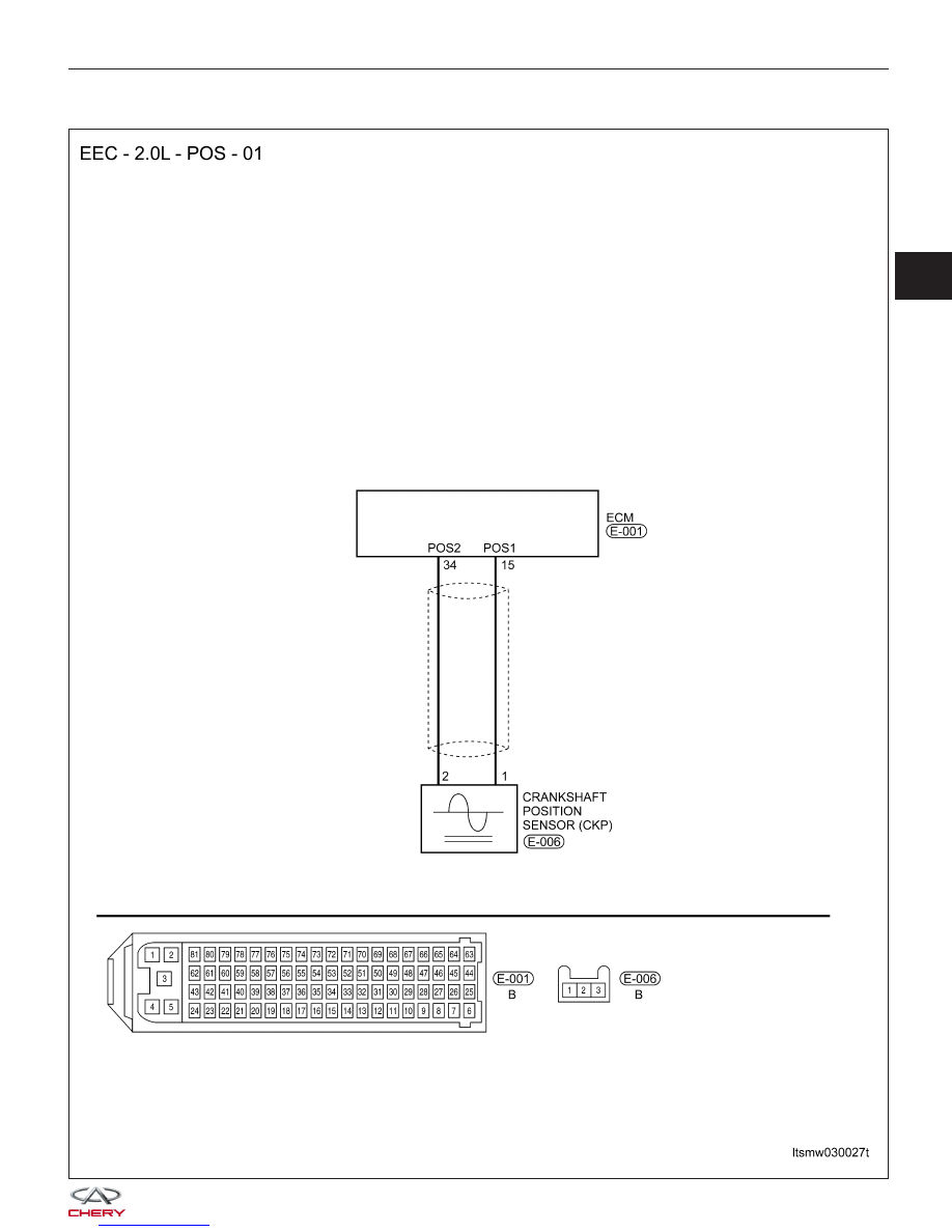
P0321 - Distributor Engine Speed In Phase Circuit Performance

DIAGNOSIS & TESTING

LTSMW030027T

03


Check reference values between ECM terminals and ground under the following conditions:

ECM TERMINAL NO.

ITEM

CONDITION

DATA (AVERAGE DC

VOLTAGE)

15

Crankshaft Position (CKP)

sensor

• Ignition switch: ON

• Engine: Not cranking

3 V

34

On Board Diagnostic Logic
• Self-diagnosis detection logic.

DTC NO.

DTC DEFINITION

DTC DETECTION

CONDITION

DTC SET

CONDITION

POSSIBLE CAUSE

P0321

Distributor engine

speed in phase

circuit performance

Engine is running

ECM detected that

the input signal is

out of the

acceptable range.

• CKP

• Crankshaft signal
plate

• Harness or
connectors

• ECM

DTC Confirmation Procedure:

Before performing the following procedure, confirm that battery voltage is more than 12 V.

• Turn ignition switch off.

• Connect the X-431 scan tool to the Data Link Connector (DLC) - use the most current software available.

• Turn ignition switch on.

• With the scan tool, record and erase stored DTCs in the ECM.

• Start engine and warm it to normal operating temperature then select view DTC.

• If DTC is detected, go to Diagnostic Procedure - Step 1.

• If the DTC is not detected, the DTC condition is intermittent (See Diagnosis & Testing Diagnostic Help in Sec-

tion 03 Electronic Engine Controls).

NOTE :
While performing electrical diagnosis & testing, always refer to the electrical schematics for specific circuit
and component information.

Diagnostic Procedure

1.

CHECK GROUND CONNECTIONS

• Turn ignition switch off.

• Loosen and retighten ground screws on the body (See Ground Inspection in Section 03 Electronic Engine Con-

trols).

• Inspect ground connections E-207 and E-208 mounting position (See Vehicle Wiring Harness Layout - Engine

Room Harness (With 2.0L Engine) in Section 16 Wiring).

Are the ground connections OK?

Yes

>>

Go to the next step.

No

>>

Repair or replace ground harness or connections.

DIAGNOSIS & TESTING


2.

CHECK CKP SENSOR ELECTRICAL CONNECTOR

• Turn ignition switch off.

• Disconnect the CKP sensor (1) electrical connector.

• Inspect the electrical connector for damage.

Is the electrical connector OK?

Yes

>>

Go to the next step.

No

>>

Repair or replace the electrical connector

as necessary.

3.

CHECK CKP SENSOR REFERENCE VOLTAGE

• Turn ignition switch on.

• Check CKP sensor supply voltage between sensor

connector E-006, terminal 1 and ground, terminal 2
and ground in the sensor electrical connector.

• 3 V should exist.

Is the check result normal?

Yes

>>

Go to step 5.

No

>>

Go to the next step.

4.

DETECT MALFUNCTIONING PART

• Check the following:

− Harness for an open or short between CKP sensor and ECM.

Is the check result normal?

Yes

>>

Replace the ECM.

NOTE : The Immobilizer control module must be matched to the new ECM (See ECM Removal & Instal-

lation in Section 03 Electronic Engine Controls).

No

>>

Repair circuit for an open or short in harness or connectors.

DIAGNOSIS & TESTING

BESM040006

LTSMD030048

03


5.

CHECK CKP SENSOR SIGNAL WAVE PATTERN

• Connect ECM connector.

• Connect CKP sensor connector.

• Check sensor output signal when engine is running.

ENGINE ANALYZER (KES-200)

CKP SENSOR SIGNAL

Is the CKP sensor output signal normal?

Yes

>>

Go to step 9.

No

>>

Go to the next step.

6.

CHECK CKP SENSOR

• Check resistance as table shown.

• Remove the sensor.

• Visually check the sensor for chipping.

TERMINAL NO.

RESISTANCE

⍀ (25°C)

1 & 2

Approximately 860

Is the check result normal?

Yes

>>

Replace the CKP sensor with a known good CKP sensor.
Monitor the CKP sensor signal on the KES-200 screen.
− If the CKP sensor signals were normal, the system is OK.
− If the CKP sensor signals were still irregular or missing, go to step 7.

No

>>

Replace CKP sensor.

DIAGNOSIS & TESTING


Content   ..  163  164  165  166   ..