Chery Tiggo. Manual - part 164


  Index      Chery     Chery Tiggo - service repair manual 2009 year


Search            


Content   ..  162  163  164  165   ..


Chery Tiggo. Manual - part 164


2.

INSPECTION START

• Start the engine.

Is any cylinder ignited?

Yes

>>

If with the X-431, go to the next step.
If without the X-431, go to step 4.

No

>>

Go to step 5.

3.

PERFORM ACTIVE TEST FUNCTION

• Start engine.

• Select ⬙ACTIVE TEST⬙ menu.

• Perform injector active test.

• Make sure that each test produces a momentary engine speed drop.

Is the check result normal?

Yes

>>

Go to step 10.

No

>>

Go to step 5.

4.

CHECK FUNCTION OF INJECTOR

• Listen to injector operating sound one by one.

Do all injectors clicking noise exist?

Yes

>>

Go to step 10.

No

>>

Go to the next step.

5.

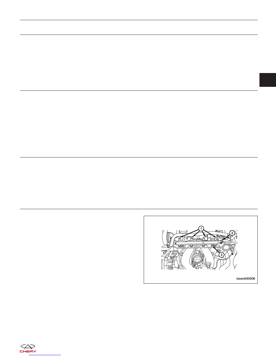
CHECK INJECTOR ELECTRICAL CONNECTOR

• Turn ignition switch off.

• Disconnect the injector electrical connector (1).

• Inspect the electrical connector for damage.

Is the electrical connector OK?

Yes

>>

Go to the next step.

No

>>

Repair or replace the electrical connector

as necessary.

DIAGNOSIS & TESTING

BESM040006

03


6.

CHECK INJECTOR POWER SUPPLY CIRCUIT FOR SHORTED

• Turn ignition switch on.

• Check injector supply voltage between sensor ter-

minal and ground in the electrical connector.

• Battery voltage should exist.

Is the check result normal?

Yes

>>

Go to step 8.

No

>>

Go to the next step.

7.

DETECT MALFUNCTIONING PART

• Check the following:

− Harness connectors A-102, E-105
− Front fuse and relay box F3
− Fuse 12, fuse 23, fuse 24
− Harness for an open or short between injector and fuse

Is the check result normal?

Yes

>>

With the X-431, check the system, If OK, go to the next step.

No

>>

Repair malfunctioning part.

8.

CHECK INJECTOR CONTROL CIRCUITS FOR A SHORT

• Check injector control circuit voltage.

• 3.6 V should exist.

Is the check result normal?

Yes

>>

Go to step 10.

No

>>

Go to the next step.

9.

DETECT MALFUNCTIONING PART

• Turn ignition switch off.

• Disconnect ECM harness connector.

• Check if the injector control circuits short to power supply circuits.

• Check the following.

• Voltage should not exist.

INJECTOR NO.

POWER SUPPLY CIRCUIT

INJECTOR TERMINAL

1

Power supply circuit

2

2

2

3

2

4

2

DIAGNOSIS & TESTING

LTSMD030024


Is the check result normal?

Yes

>>

Replace the ECM.

NOTE : The Immobilizer control module must be matched to the new ECM (See ECM Removal & Instal-

lation in Section 03 Electronic Engine Controls).

No

>>

Repair circuit for a short in harness or connectors.

10.

CHECK INJECTOR RESISTANCE

• Check resistance as table shown.

• Check the fuel injector resistance as shown in the following:

INJECTOR

NO.

INJECTOR

TERMINAL

RESISTANCE

(APPROXIMATELY)

(20°C)

1

1 & 2

11 - 16

2

1 & 2

3

1 & 2

4

1 & 2

• Connect ECM connector.

• Connect injector connector.

• Check the fuel injector voltage as shown in the following:

TERMINAL NO.

ITEM

CONDITION

DATA (AVERAGE DC

VOLTAGE)

6

Injector 2

• Engine is running

• Warm-up condition

• Idle

• Accelerate suddenly

Voltage: 11 V - 14 V

7

Injector 3

27

Injector 1

47

Injector 4

Is the check result normal?

Yes

>>

Go to the next step.

No

>>

Replace injector.

DIAGNOSIS & TESTING

03


11.

CHECK DTC

• With the X-431 scan tool, read ECM DTCs.

• See ⬙DTC Confirmation Procedure⬙.

Is DTC P0262, P0265, P0268 or P0271 still present?

Yes

>>

Replace the ECM.

NOTE : The Immobilizer control module must be matched to the new ECM (See ECM Removal & Instal-

lation in Section 03 Electronic Engine Controls).

No

>>

The system is now operating properly.
Reassemble the vehicle and road test to verify the customers complaint is repaired.

DIAGNOSIS & TESTING


Content   ..  162  163  164  165   ..