Chery Tiggo. Manual - part 162


  Index      Chery     Chery Tiggo - service repair manual 2009 year


Search            


Content   ..  160  161  162  163   ..


Chery Tiggo. Manual - part 162


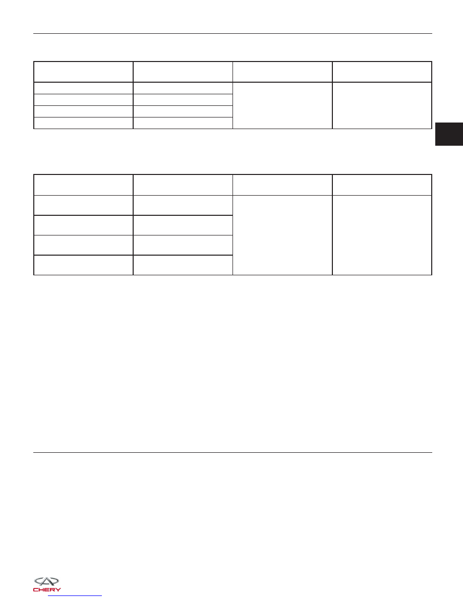
Check reference values between ECM terminals and ground under the following conditions:

ECM TERMINAL NO.

ITEM

CONDITION

DATA (AVERAGE DC

VOLTAGE

6

Injector 2

• Engine is running

• Warm-up condition

• Idle

• Accelerate suddenly

Voltage: 11 - 14 V

7

Injector 3

27

Injector 1

47

Injector 4

On Board Diagnostic Logic
• Self-diagnosis detection logic.

DTC NO.

DTC DEFINITION

DTC DETECTION

CONDITION

POSSIBLE CAUSE

P0261

Cylinder 1 - Injector Circuit

Low

Engine is running

• Injector

• Harness or connectors

• ECM

P0264

Cylinder 2 - Injector Circuit

Low

P0267

Cylinder 3 - Injector Circuit

Low

P0270

Cylinder 4 - Injector Circuit

Low

DTC Confirmation Procedure:

Before performing the following procedure, confirm that battery voltage is more than 12 V.

• Turn ignition switch off.

• Connect the X-431 scan tool to the Data Link Connector (DLC) - use the most current software available.

• Turn ignition switch on.

• With the scan tool, record and erase stored DTCs in the ECM.

• Start engine and warm it to normal operating temperature then select view DTC.

• If DTC is detected, go to Diagnostic Procedure - Step 1.

• If the DTC is not detected, the DTC condition is intermittent (See Diagnosis & Testing Diagnostic Help in Sec-

tion 03 Electronic Engine Controls).

NOTE :
While performing electrical diagnosis & testing, always refer to the electrical schematics for specific circuit
and component information.

Diagnostic Procedure

1.

CHECK GROUND CONNECTIONS

• Turn ignition switch off.

• Loosen and retighten ground screws on the body (See Ground Inspection in Section 03 Electronic Engine Con-

trols).

• Inspect ground connections E-207 and E-208 mounting position (See Vehicle Wiring Harness Layout - Engine

Room Harness (With 2.0L Engine) in Section 16 Wiring).

Are the ground connections OK?

Yes

>>

Go to the next step.

No

>>

Repair or replace ground harness or connections.

DIAGNOSIS & TESTING

03


2.

INSPECTION START

• Start the engine.

Is any cylinder ignited?

Yes

>>

If with the X-431, go to the next step.
If without the X-431, go to step 4.

No

>>

Go to step 5.

3.

PERFORM ACTIVE TEST FUNCTION

• Select ⬙ACTIVE TEST⬙ menu.

• Perform injector active test.

• Make sure that each test produces a momentary engine speed drop.

Is the check result normal?

Yes

>>

Go to step 10.

No

>>

Go to step 5.

4.

CHECK FUNCTION OF INJECTOR

• Listen to injector operating sound one by one.

Do all injectors clicking noise exist?

Yes

>>

Go to step 10.

No

>>

Go to the next step.

5.

CHECK INJECTOR ELECTRICAL CONNECTOR

• Turn ignition switch off.

• Disconnect the injector electrical connector (1).

• Inspect the electrical connector for damage.

Is the electrical connector OK?

Yes

>>

Go to the next step.

No

>>

Repair or replace the electrical connector

as necessary.

DIAGNOSIS & TESTING

BESM040006


6.

CHECK INJECTOR POWER SUPPLY CIRCUIT FOR AN OPEN

• Turn ignition switch on.

• Check injector supply voltage between sensor ter-

minal and ground in the electrical connector.

• Battery voltage should exist.

Is the check result normal?

Yes

>>

Go to step 8.

No

>>

Go to the next step.

7.

DETECT MALFUNCTIONING PART

• Check the following:

− Harness connectors A-102, E-105
− Front fuse and relay box F3
− Fuse 12, fuse 23, fuse 24
− Harness for shorted between injector and fuse

Is the check result normal?

Yes

>>

Go to the next step.

No

>>

Repair malfunctioning part.

8.

CHECK INJECTOR CONTROL CIRCUITS FOR A SHORT

• Check injector control circuit voltage.

• 3.6 V should exist.

Is the check result normal?

Yes

>>

Go to step 10.

No

>>

Go to the next step.

DIAGNOSIS & TESTING

LTSMD030024

03


9.

DETECT MALFUNCTIONING PART

• Turn ignition switch off.

• Disconnect ECM harness connector (1).

• Check for harness continuity between the following terminals.

• Continuity should not exist.

INJECTOR NO.

INJECTOR

TERMINAL

GROUND

1

2

Ground

2

2

3

2

4

2

Is the check result normal?

Yes

>>

Replace the ECM.

NOTE : The Immobilizer control module must be matched to the new ECM (See ECM Removal & Instal-

lation in Section 03 Electronic Engine Controls).

No

>>

Repair circuit for a short in harness or connectors.

DIAGNOSIS & TESTING

LTSMD030077


Content   ..  160  161  162  163   ..