Chery Tiggo. Manual - part 128


  Index      Chery     Chery Tiggo - service repair manual 2009 year


Search            


Content   ..  126  127  128  129   ..


Chery Tiggo. Manual - part 128


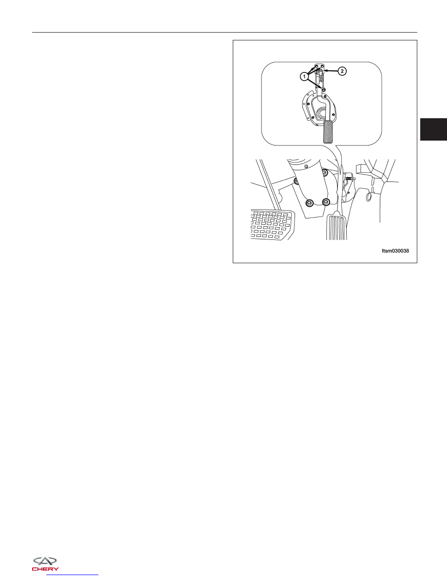
3. Disconnect the APP sensor electrical connector (2).

4. Remove the three APP sensor mounting bolts (1).

(Tighten: APP sensor mounting bolts to 11 N·m)

5. Remove the APP sensor with the pedal.

6. Installation is in the reverse order of removal.

Electronic Throttle Control Actuator

Description

The throttle body is located on the intake manifold. It controls air into the intake manifold. The electronic throttle
control actuator consists of throttle control motor, throttle position sensor, etc. The throttle control motor is operated
by the Engine Control Module (ECM) and it opens and closes the throttle valve. The throttle position sensor detects
the throttle valve position.

Operation

Filtered air from the air cleaner enters the intake manifold through the throttle body. A throttle valve (plate) is used to
supply air for idle and driving conditions. The throttle position sensor is part the throttle body. The throttle position
sensor signal is used by the ECM to determine throttle position. The ECM controls the electronic throttle control to
meter air into the engine. This regulates engine power. The vehicle is in sense a “Drive by Wire” system.

Removal & Installation

1. Remove the engine cover.

2. Disconnect the negative battery cable.

ON-VEHICLE SERVICE

LTSM030038

03


3. Disconnect the electronic throttle control actuator

connector.

4. Remove two hoses on electronic throttle control

actuator.

5. Remove four electronic throttle control actuator

mounting bolts.
(Tighten: Electronic throttle control actuator bolts to
10 N·m)

6. Remove the throttle control actuator carefully.

7. Installation is in the reverse order of removal.

Engine Control Module (ECM)

Description

The Engine Control Module (ECM) for this model is serviced only as a complete unit.

Operation

The ECM is a pre-programmed, microprocessor-based digital computer. It regulates ignition timing, air-fuel ratio,
emission control devices, charging system, certain transmission features, speed control, air conditioning compressor
clutch engagement and idle speed. The ECM can adapt its programming to meet changing operating conditions.

Removal & Installation

1. Disconnect the negative battery cable.

2. Remove the glove box (See Instrument Panel Removal & Installation in Section 15 Body).

3. Disconnect the ECM electrical connector.

4. Remove the ECM retaining bolts (1).

(Tighten: ECM retaining bolts to 10 N·m)

5. Remove the ECM.

6. Installation is in the reverse order of removal.

Installation Notes:

NOTE :
The Immobilizer control module must be matched to
the new ECM before the vehicle will start.

Matching Immobilizer Control Module to New
Engine Control Module (ECM)

Perform the following to match the Immobilizer control
module to the new ECM:

− With the X-431 scan tool, choose T11 series.
− Choose

⬙immobilize⬙.

− Choose

⬙input code⬙.

− Input the safety code.
− Click the small keyboard.
− Click

⬙OK⬙.

− Choose

⬙Immobilizer adapt⬙.

− Choose

⬙read Immobilizer to ECM⬙ immedi-

ately.

− Click

⬙OK⬙.

ON-VEHICLE SERVICE

BESM030022

LTSM030025


2.0L ENGINE CONTROLS

GENERAL INFORMATION

03-229

Description

03-229

Operation

03-229

Electronic Engine Control Input & Output
Device Failure Modes

03-230

Specifications

03-231

Special Tools

03-232

Electrical Schematics

03-234

ECM Connector Pin-Out Table

03-245

DIAGNOSIS & TESTING

03-247

Diagnostic Help

03-247

Ground Inspection

03-247

Electronic Throttle Control Actuator
Self-Learning Operation Introduction

03-247

Diagnostic Tools

03-248

Diagnostic Trouble Code (DTC) List

03-250

ECM Power Supply and Ground Circuit
Test

03-254

Power Supply And Ground Circuit
Diagnostic Check

03-254

Diagnostic Trouble Code (DTC) Tests

03-261

P0016 - Camshaft Position-Crankshaft
Position Correlation Error

03-261

P0031 - O

2

Sensor 1 Heater Control

Circuit Low

03-272

P0032 - O

2

Sensor 1 Heater Control

Circuit High

03-277

P0102 - Mass Or Volume Air Flow
Circuit Low Input

03-282

P0103 - Mass Or Volume Air Flow
Circuit High Input

03-288

P0112 - Intake Air Temperature Circuit
Low Input

03-293

P0113 - Intake Air Temperature Circuit
High Input

03-297

P0117 - Engine Coolant Temperature
Circuit Low Input

03-301

P0118 - Engine Coolant Temperature
Circuit High Input

03-305

P0122 - Throttle Position Sensor A
Circuit Low Input

03-310

P0123 - Throttle Position Sensor A
Circuit High Input

03-316

P0132 - O

2

Sensor Circuit 1 High

Voltage

03-322

P0171 - Fuel Trim System Too Lean

03-326

P0172 - Fuel Trim System Too Rich

03-336

P0201 - Cylinder 1 - Injector Circuit,
P0202 - Cylinder 2 - Injector Circuit,
P0203 - Cylinder 3 - Injector Circuit,
P0204 - Cylinder 4 - Injector Circuit

03-345

P0221 - Throttle Position Sensor B
Performance

03-352

P0261 - Cylinder 1 Injector Circuit Low,
P0264 - Cylinder 2 Injector Circuit Low,
P0267 - Cylinder 3 Injector Circuit Low,
P0270 - Cylinder 4 Injector Circuit Low

03-359

P0262 - Cylinder 1 Injector Circuit High,
P0265 - Cylinder 2 Injector Circuit High,
P0268 - Cylinder 3 Injector Circuit High,
P0271 - Cylinder 4 Injector Circuit High

03-366

P0321 - Distributor Engine Speed In
Phase Circuit Performance

03-373

P0324 - Knock Control System Error

03-378

P0343 - Camshaft Position Sensor
Circuit High Input

03-383

P0444 - Evaporative Emission System
Purge Control Valve Circuit Open

03-389

P0506 - Idle Control System RPM
Lower Than Expected

03-394

P0604 - Internal Controller Module
Random Access Memory (RAM) Error,
P0605 - Internal Controller Module
ROM Test Error, P0606 - ECM
Processor

03-396

P0602 - ECM Programming Error

03-398

P0645 - A/C Clutch Relay Circuit

03-400

P1545 - Throttle Position Control
Performance

03-405

P2138 - Pedal Position Sensor
Performance

03-413

U0001 - High Speed CAN Defective

03-420

ON-VEHICLE SERVICE

03-427

Engine Coolant Temperature (ECT)
Sensor

03-427

Description

03-427

Operation

03-427

Removal & Installation

03-427

Knock Sensor

03-428

Description

03-428

Operation

03-428

Removal & Installation

03-428

Oxygen Sensor

03-428

Description

03-428

Operation

03-428

Upstream Oxygen Sensor

03-429

Downstream Oxygen Sensor

03-429

Removal & Installation - Upstream
Oxygen Sensor

03-429

Removal & Installation - Downstream
Oxygen Sensor

03-429

Crankshaft Position (CKP) Sensor

03-430

Description

03-430

Operation

03-430

Removal & Installation

03-430

03


Camshaft Position (CMP) Sensor

03-431

Description

03-431

Operation

03-431

Removal & Installation

03-431

Air Flow Sensor

03-431

Description

03-431

Operation

03-431

Removal & Installation

03-431

Accelerator Sensor

03-432

Description

03-432

Operation

03-432

Removal & Installation

03-432

Speed Control System

03-432

Description

03-432

Operation

03-433

Electrical Schematics

03-434

Accelerator Pedal Position (APP)
Sensor

03-438

Description

03-438

Operation

03-438

Removal & Installation

03-438

Electronic Throttle Control Actuator

03-439

Description

03-439

Operation

03-439

Removal & Installation

03-439

Engine Control Module (ECM)

03-440

Description

03-440

Operation

03-440

Removal & Installation

03-440

ELECTRONIC ENGINE CONTROLS - 2.0L ENGINE CONTROLS


Content   ..  126  127  128  129   ..