Chery Tiggo. Manual - part 126


  Index      Chery     Chery Tiggo - service repair manual 2009 year


Search            


Content   ..  124  125  126  127   ..


Chery Tiggo. Manual - part 126


ON-VEHICLE SERVICE

Engine Coolant Temperature (ECT) Sensor

Description

The Engine Coolant Temperature (ECT) sensor threads into the coolant outlet connector. The ECT is a negative
thermal coefficient sensor.

Operation

The ECT provides an input to the Engine Control Module (ECM). As temperature increases, resistance of the sensor
decreases. As coolant temperature varies, the ECT sensor resistance changes resulting in a different voltage value
at the ECT sensor signal circuit. The ECM uses the input to control air-fuel mixture, timing, A/C compressor and
radiator fan on/off times.

Removal & Installation

1. Disconnect the negative battery cable.

2. Drain the cooling system (See Cooling System Draining Procedure in Section 06 Cooling System).

WARNING!

Never remove the pressure relief cap under any conditions while the engine is operating or hot. Failure to follow
these instructions could result in personal injury or damage to the cooling system or engine. To avoid having
scalding hot coolant or steam blow out of the cooling system, use extreme care when removing the pressure
relief cap. Wait until the engine has cooled, then wrap a thick cloth around the pressure relief cap and turn it
slowly one turn (counterclockwise). Step back while the pressure is released from the cooling system. When you
are certain all the pressure has been released, (with a cloth) turn and remove the pressure relief cap. Failure to
follow these instructions may result in serious personal injury.

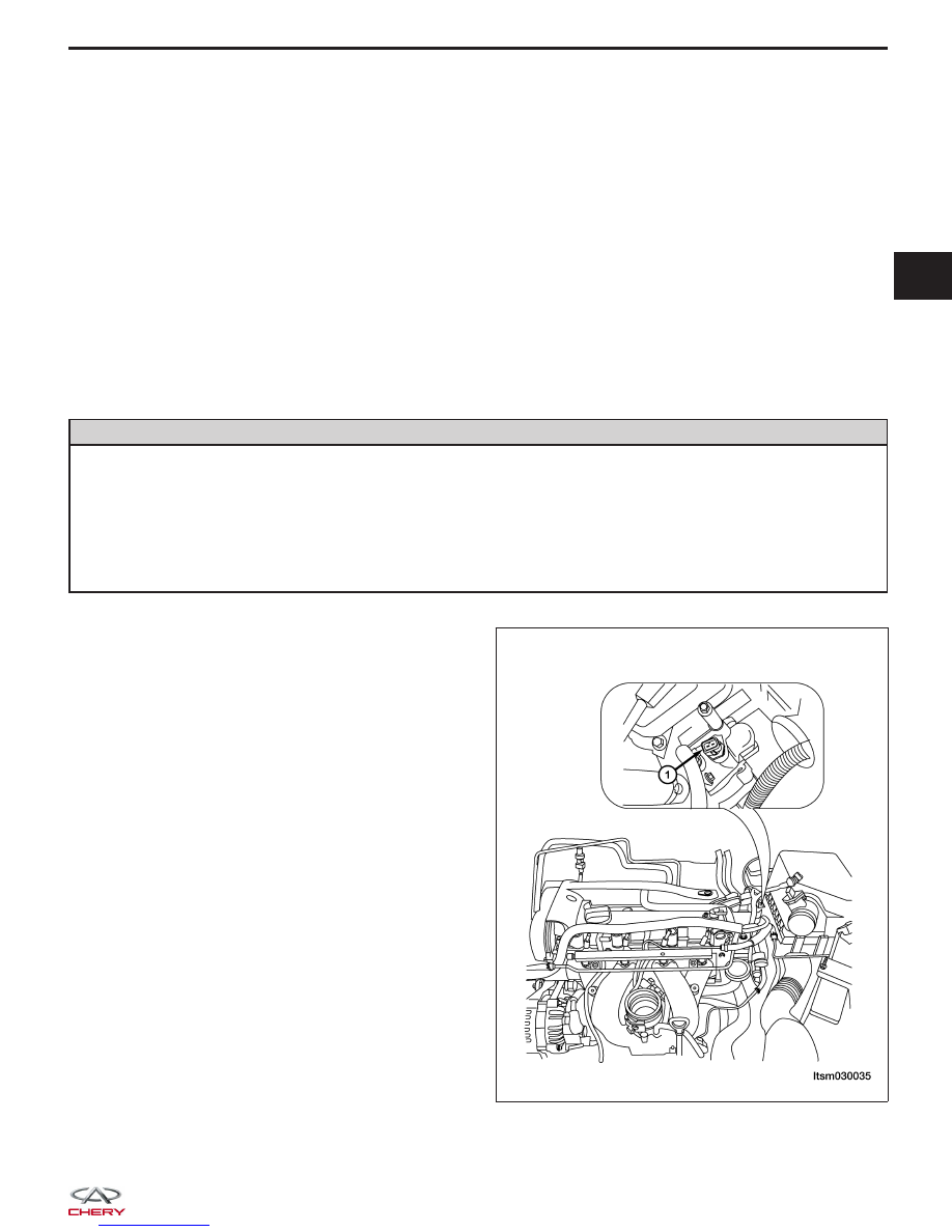
3. Disconnect the coolant temperature sensor electri-

cal connector.

CAUTION:
Remove the coolant temperature sensor when
the engine is cold.

4. Remove the engine coolant temperature sensor

(1).
(Tighten: Engine coolant temperature sensor to 20
N·m)

5. Discard the O-ring.

LTSM030035

03


6. Installation is in the reverse order of removal.

NOTE :
After installed the engine coolant temperature sensor, check the coolant level.

Knock Sensor

Description

The knock sensor is attached to the cylinder block. The knock sensor is designed to detect engine vibration that is
caused by detonation.

Operation

When the knock sensor detects a knock in one of the cylinders, it sends an input signal to the Engine Control Module
(ECM). In response, the ECM retards ignition timing for all cylinders by a specified amount.

Knock sensors contain a piezoelectric material which constantly vibrates and sends an input voltage (signal) to the
ECM while the engine operates. As the intensity of the crystal’s vibration increases, the knock sensor output voltage
also increases.

The ECM ignores knock sensor input during engine idle conditions. Once the engine speed exceeds a specified
value, knock retard is allowed.

Removal & Installation

1. Disconnect the negative battery cable.

2. Disconnect the knock sensor electrical connector.

3. Remove the knock sensor retaining bolt (1) and

remove the knock sensor.
(Tighten: Knock sensor retaining bolt to 20 N·m)

4. Installation is in the reverse order of removal.

Oxygen Sensor

Description

This vehicle is equipped with two oxygen sensors (upstream oxygen sensor & downstream oxygen sensor). The oxy-
gen sensors are located before and after the three way catalyst. The oxygen sensors continually monitor the oxygen
level in the exhaust gas. The sensor is made of ceramic zirconia. The zirconia generates voltage from approximately
1 volt in richer conditions to 0 volt in leaner conditions.

Operation

The O

2

sensors produce voltages from 0 to 1 volt, depending upon the oxygen content of the exhaust gas. When a

large amount of oxygen is present (caused by a lean air/fuel mixture, can be caused by misfire and exhaust leaks),
the sensors produces a low voltage. When there is a lesser amount of oxygen present (caused by a rich air/fuel
mixture, can be caused by internal engine problems) it produces a higher voltage. By monitoring the oxygen content
and converting it to electrical voltage, the sensors act as a rich-lean switch.

The oxygen sensors are equipped with a heating element that keeps the sensors at proper operating temperature
during all operating modes. Maintaining correct sensor temperature at all times allows the system to enter into closed
loop operation sooner. Also, it allows the system to remain in closed loop operation during periods of extended idle.

ON-VEHICLE SERVICE

BESM030018


Upstream Oxygen Sensor

The input from the upstream heated oxygen sensor tells the Engine Control Module (ECM) the oxygen content of the
exhaust gas. Based on this input, the ECM fine tunes the air-fuel ratio by adjusting injector pulse width.

Downstream Oxygen Sensor

The downstream heated oxygen sensor signal is used to detect catalytic convertor deterioration. As the convertor
deteriorates, the signal from the downstream sensor begins to match the upstream sensor signal except for a slight
time delay. By comparing the downstream heated oxygen sensor signal to the signal from the upstream sensor, the
ECM calculates catalytic convertor efficiency. This calculation is also used to establish the upstream O2 goal voltage
(switching point).

Removal & Installation - Upstream Oxygen Sensor

1. Disconnect the negative battery cable.

2. Disconnect the oxygen sensor electrical connector.

CAUTION:
Remove the oxygen sensor after the exhaust pipe has cooled.

3. Remove the upstream oxygen sensor (1).

(Tighten: Upstream oxygen sensor to 45 N·m)

4. Installation is in the reverse order of removal.

Installation Notes:
• Before installing the oxygen sensor, coat the threads with rust inhibiting lubricant.

Removal & Installation - Downstream Oxygen Sensor

1. Disconnect the negative battery cable.

2. Disconnect the oxygen sensor electrical connector.

CAUTION:
Remove the oxygen sensor after the exhaust pipe has cooled.

3. Remove the downstream oxygen sensor (2).

(Tighten: Downstream oxygen sensor to 45 N·m)

ON-VEHICLE SERVICE

BESM030017

BESM030017

03


4. Installation is in the reverse order of removal.

Installation Notes:
• Before installing the oxygen sensor, coat the threads with rust inhibiting lubricant.

Crankshaft Position (CKP) Sensor

Description

The Crankshaft Position (CKP) sensor is located on the flywheel shell facing the gear teeth of the signal plate. It
detects the fluctuation of the engine revolution. The sensor consists of a permanent magnet and induction coil.

Operation

The crankshaft sensor is made of a toothed metal disk mounted on the crankshaft and a stationary detector that
covers a magnetic coil that the current passes through. As the metal teeth move past the coil, its magnetic field is
disturbed. This causes a stream of pulses in the current. The Engine Control Module (ECM) can calculate the speed
of the engine from the crankshaft’s frequency of pulses

Removal & Installation

1. Disconnect the negative battery cable.

2. Disconnect the CKP sensor electrical connector.

3. Remove the CKP sensor retaining bolt (1) and

remove the CKP sensor.
(Tighten: Crankshaft position sensor retaining bolt
to 10 N·m)

4. Installation is in the reverse order of removal.

Camshaft Position (CMP) Sensor

Description

The Camshaft Position (CMP) sensor senses the protrusion of inlet valve cam sprocket to identify a particular cyl-
inder. The CMP sensor senses the piston position. When the Crankshaft Position (CKP) sensor becomes inoperative,
the CMP sensor provides various controls of engine parts instead, utilizing timing of cylinder identification signals.
The sensor consists of a permanent magnet and Hall IC.

ON-VEHICLE SERVICE

LTSM030036


Content   ..  124  125  126  127   ..