Index Chery Chery Tiggo - service repair manual 2009 year
Search
Content .. 98 99 100 101 ..
Chery Tiggo. Manual - part 100
DIAGNOSIS & TESTING
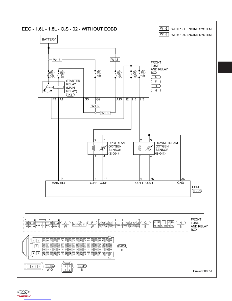
LTSMW030055T
03