Chery Tiggo. Manual - part 98


  Index      Chery     Chery Tiggo - service repair manual 2009 year


Search            


Content   ..  96  97  98  99   ..


Chery Tiggo. Manual - part 98


6.

CHECK THE TPS RESISTANCE

• Check resistance between TPS terminal 2 and terminal 3.

• 2 k⍀ ± 20 % (20°C) should exist.

• Also check the resistance between TPS terminal 6 and terminal 2 while turn the throttle.

• The resistance should linear change.

Is the check result normal?

Yes

>>

Go to the next step.

No

>>

Replace the TPS.
Perform the TPS self-learning.

7.

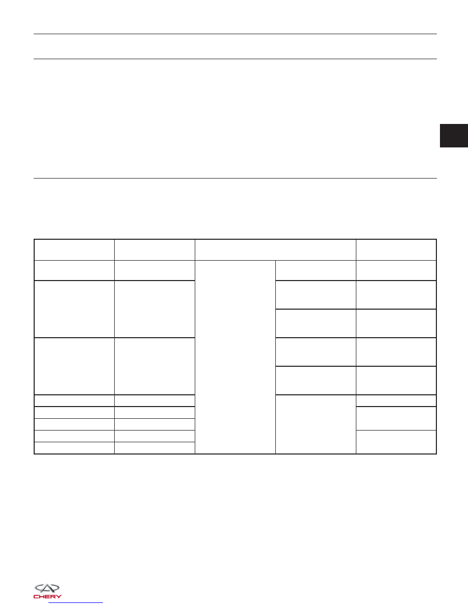
CHECK THE TPS SIGNAL

• Turn ignition switch off.

• Connect ECM connector.

• Connect TPS connector.

• Turn ignition switch on.

• Check voltage between TPS terminal 3 and ground under the following conditions:

ECM TERMINAL

NO.

ITEM

CONDITION

DATA (DC

VOLTAGE)

32

Regulated sensor

supply

Ignition switch: ON

-

Approximately 5 V

38

Electronic throttle

control actuator

(Position sensor)

• Engine stopped

• Accelerator pedal:
Fully released

4.24 V

• Engine stopped

• Accelerator pedal:
Fully depressed

0.72 V

54

Electronic throttle

control actuator

• Engine stopped

• Accelerator pedal:
Fully released

0.74 V

• Engine stopped

• Accelerator pedal:
Fully depressed

4.62 V

78

Sensor (GND)

-

Approximately 0 V

64

Motor 4

12 V or 0 V

65

Motor 3

66

Motor 2

12 V or 0 V

67

Motor 1

Is the check result normal?

Yes

>>

Go to the next step.

No

>>

Replace the TPS.
Perform the TPS self-learning.

DIAGNOSIS & TESTING

03


8.

CHECK DTC

• With the X-431 scan tool, read ECM DTCs.

• Refer to ⬙DTC Confirmation Procedure⬙.

Is DTC P0122 still present?

Yes

>>

Replace the ECM.

NOTE : The Immobilizer control module must be matched to the new ECM (See ECM Removal & Instal-

lation in Section 03 Electronic Engine Controls).

No

>>

The system is now operating properly.
Reassemble the vehicle and road test to verify the customers complaint is repaired.

DIAGNOSIS & TESTING


P0123 - Throttle Position Sensor A Circuit High Input

DIAGNOSIS & TESTING

LTSMW030044T

03


Check reference values between ECM terminals and ground under the following conditions:

ECM TERMINAL

NO.

ITEM

CONDITION

DATA (DC

VOLTAGE)

32

Regulated sensor

supply

Ignition switch: ON

-

Approximately 5 V

38

Electronic throttle

control actuator

(Position sensor)

• Engine stopped

• Accelerator pedal:
Fully released

4.24 V

• Engine stopped

• Accelerator pedal:
Fully depressed

0.72 V

54

Electronic throttle

control actuator

• Engine stopped

• Accelerator pedal:
Fully released

0.74 V

• Engine stopped

• Accelerator pedal:
Fully depressed

4.62 V

78

Sensor (GND)

-

Approximately 0 V

64

Motor 4

12 V or 0 V

65

Motor 3

66

Motor 2

12 V or 0 V

67

Motor 1

On Board Diagnostic Logic
• Self-diagnosis detection logic.

DTC NO.

DTC DEFINITION

DTC DETECTION

CONDITION

DTC SET

CONDITION

POSSIBLE CAUSE

P0123

TPS A circuit high

input

• Ignition switch:
ON

• Engine: Running

Signal output is
above maximum
acceptable range for
a few seconds
continuously.

• Throttle Position
Sensor (TPS) or
misalignment

• Harness or
connectors (The
sensor signal circuit
is open or shorted)

• ECM

DTC Confirmation Procedure:

Before performing the following procedure, confirm that battery voltage is more than 12 V.

• Turn ignition switch off.

• Connect the X-431 scan tool to the Data Link Connector (DLC) - use the most current software available.

• Turn ignition switch on.

• With the scan tool, record and erase stored DTCs in the ECM.

• Start engine and warm it to normal operating temperature, then select view DTC and data stream.

• If the DTC is detected, the DTC condition is current. Go to Diagnostic Procedure - Step 1.

• If the DTC is not detected, the DTC condition is intermittent (See Diagnostic Help and Intermittent DTC Trou-

bleshooting in Section 03 Electronic Engine Controls for more information.

NOTE :
While performing electrical diagnosis & testing, always refer to the electrical schematics for specific circuit
and component information.

DIAGNOSIS & TESTING


Content   ..  96  97  98  99   ..