Chery Tiggo. Manual - part 97


  Index      Chery     Chery Tiggo - service repair manual 2009 year


Search            


Content   ..  95  96  97  98   ..


Chery Tiggo. Manual - part 97


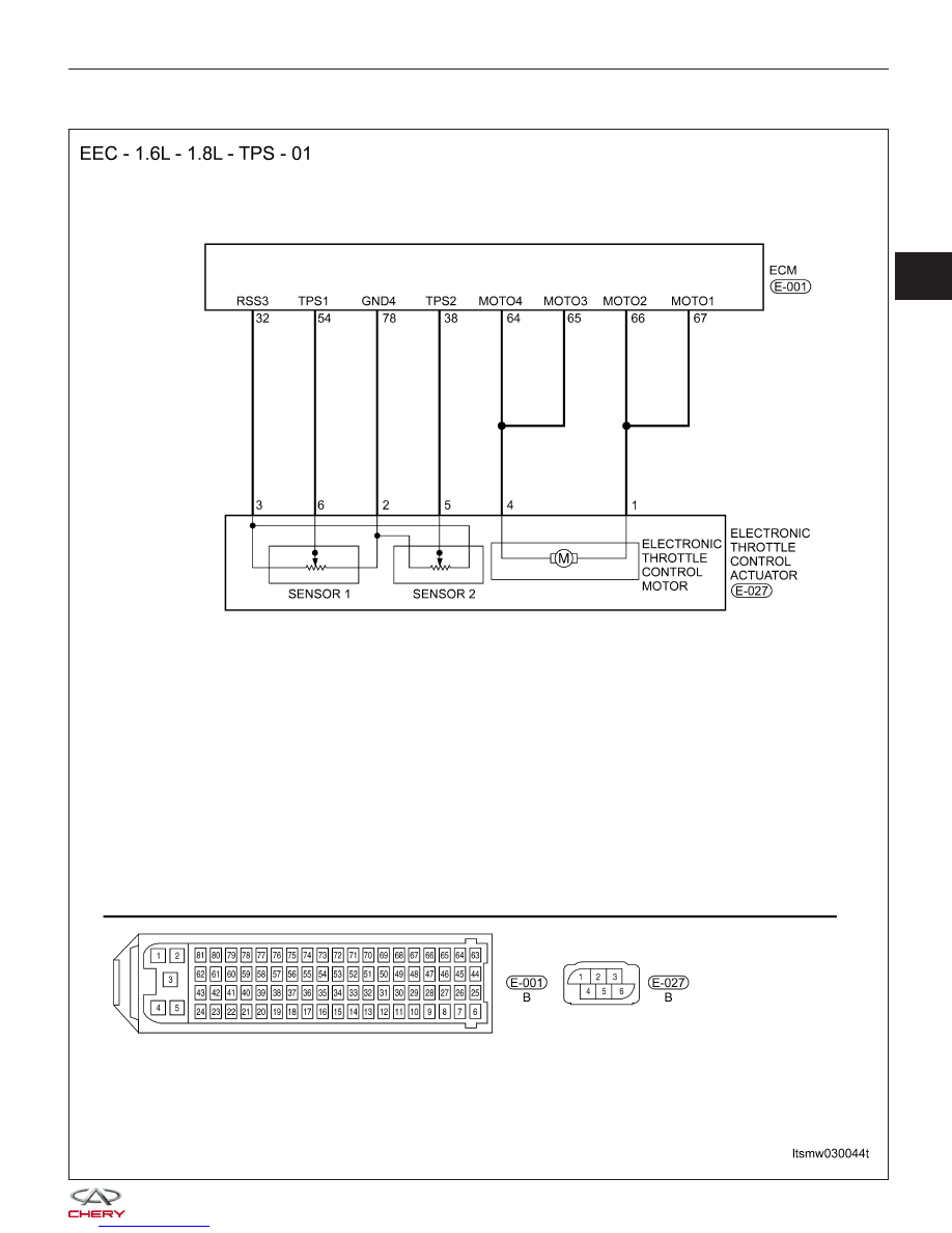
P0122 - Throttle Position Sensor A Circuit Low Input

DIAGNOSIS & TESTING

LTSMW030044T

03


Check reference values between ECM terminals and ground under the following conditions:

ECM TERMINAL

NO.

ITEM

CONDITION

DATA (DC

VOLTAGE)

32

Regulated sensor

supply

Ignition switch: ON

-

Approximately 5 V

38

Electronic throttle

control actuator

(Position sensor)

• Engine stopped

• Accelerator pedal:
Fully released

4.24 V

• Engine stopped

• Accelerator pedal:
Fully depressed

0.72 V

54

Electronic throttle

control actuator

• Engine stopped

• Accelerator pedal:
Fully released

0.74 V

• Engine stopped

• Accelerator pedal:
Fully depressed

4.62 V

64

Motor 4

-

12 V or 0 V

65

Motor 3

66

Motor 2

12 V or 0 V

67

Motor 1

78

Sensor (GND)

Approximately 0 V

On Board Diagnostic Logic
• Self-diagnosis detection logic.

DTC NO.

DTC DEFINITION

DTC DETECTION

CONDITION

DTC SET

CONDITION

POSSIBLE CAUSE

P0122

Throttle Position

Sensor (TPS) A

circuit low input

• Ignition switch:
ON

• Engine: Running

Signal output is
below minimum
acceptable range for
a few seconds
continuously.

• Throttle Position
Sensor (TPS) or
misalignment

• Harness or
connectors (Signal
circuit is open or
shorted)

• ECM

DTC Confirmation Procedure:

Before performing the following procedure, confirm that battery voltage is more than 12 V.

• Turn ignition switch off.

• Connect the X-431 scan tool to the Data Link Connector (DLC) - use the most current software available.

• Turn ignition switch on.

• With the scan tool, record and erase stored DTCs in the ECM.

• Start engine and warm it to normal operating temperature, then select view DTC and data stream.

• If the DTC is detected, the DTC condition is current. Go to Diagnostic Procedure - Step 1.

• If the DTC is not detected, the DTC condition is intermittent (See Diagnostic Help and Intermittent DTC Trou-

bleshooting in Section 03 Electronic Engine Controls for more information.

NOTE :
While performing electrical diagnosis & testing, always refer to the electrical schematics for specific circuit
and component information.

DIAGNOSIS & TESTING


Diagnostic Procedure

1.

CHECK GROUND CONNECTIONS

• Turn ignition switch off.

• Loosen and retighten ground screws on the body (See Ground Inspection in Section 03 Electronic Engine Con-

trols).

• Inspect ground connections E-207 and E-208 mounting position (See Vehicle Wiring Harness Layout - Engine

Room Harness (With 1.6L/1.8L Engine) in Section 16 Wiring).

Are the ground connections OK?

Yes

>>

Go to the next step.

No

>>

Repair or replace ground connections.

2.

CHECK TPS ELECTRICAL CONNECTOR

• Disconnect the TPS (1) electrical connector.

• Inspect the electrical connector for damage.

Is the electrical connector OK?

Yes

>>

Go to the next step.

No

>>

Repair or replace the electrical connector

as necessary.

DIAGNOSIS & TESTING

VISMD030203

03


3.

CHECK THE THROTTLE POSITION SENSOR (TPS) POWER SUPPLY CIRCUIT

• Turn ignition switch on.

• Check supply voltage between the TPS terminal 3

and ground in the sensor electrical connector
E-027.

• 5 V should exist.

Is the check result normal?

Yes

>>

Go to the next step.

No

>>

Repair circuit for an open or short to
ground in harness or connectors.
If harness is normal, replace the ECM.

NOTE : The Immobilizer control module

must be matched to the new ECM (See ECM Removal & Installation in Section 03 Electronic
Engine Controls).

4.

CHECK TPS SIGNAL CIRCUIT FOR AN OPEN OR SHORT

• Turn ignition switch off.

• Disconnect ECM harness connector.

• Check harness continuity between following terminals.

TPS SENSOR CONNECTOR TERMINAL

ECM CONNECTOR TERMINAL

3

32

• Continuity should exist.

• Check TPS signal circuit

• Check harness for a short to power.

Is the check result normal?

Yes

>>

Go to step 6.

No

>>

Go to the next step.

5.

DETECT MALFUNCTIONING PART

• Check harness for an open or short to ground between TPS connector terminal 2 and ECM connector E-001,

terminal 78.

Is the check result normal?

Yes

>>

Go to the next step.

No

>>

Repair or replace harness or connectors.

DIAGNOSIS & TESTING

LTSMD030035


Content   ..  95  96  97  98   ..