Chery Tiggo. Manual - part 79
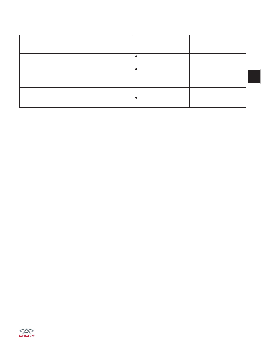
Check reference values between ECM terminals and ground under the following conditions:
ECM TERMINAL NO.
ITEM
CONDITION
DATA (DC VOLTAGE)
12
Continuous Supply
Voltage
-
Voltage (11 - 14 V)
13
Ignition Switch
€ Ignition switch: ON
Voltage (11 - 14 V)
€ Ignition switch: OFF
Approximately 0 V
14
EMS Relay (Main Relay)
€ Ignition switch: OFF
€ More than a few
seconds after turning
ignition switch OFF
Voltage (11 - 14 V)
44
45
Switched Supply Voltage
(SSV)
€ Ignition switch: ON
Voltage (11 - 14 V)
63
DIAGNOSIS & TESTING
03