Chery Tiggo. Manual - part 80


  Index      Chery     Chery Tiggo - service repair manual 2009 year


Search            


Content   ..  78  79  80  81   ..


Chery Tiggo. Manual - part 80


7.

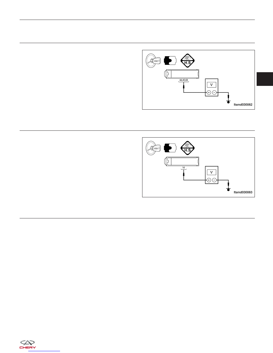
CHECK ECM POWER SUPPLY CIRCUIT - (2)

•  Check voltage between ECM terminals 44, 45, 63

 and ground.

•  Voltage: Turn ignition switch on, battery voltage

 should exist and after turning ignition switch off,
 battery voltage will exist a few seconds, then drop
 to approximate 0 V.

Is the check result normal?

Yes

>>

Check the starting system.

No

>>

Go to the next step.

8.

CHECK STARTER RELAY (K4) SUPPLY VOLTAGE

•  Turn ignition switch off. Wait for at least 10 sec-

 onds.

•  Check voltage between the ECM terminal 14 and

 ground.

• Battery voltage should exist.

Is the check result normal?

Yes

>>

Go to the next step.

No

>>

Go to step 10.

9.

CHECK ECM POWER SUPPLY CIRCUIT - (3)

•  Disconnect ECM harness connector.

•  Disconnect ECM power supply circuit connector F in front fuse and relay box harness connector.

•  Check harness continuity between ECM terminals 44, 45, 63 and front fuse and relay box terminal F3.

•  Continuity should exist.

•  Also check harness for a short to ground and short to power.

Is the check result normal?

Yes

>>

Go to step 11.

No

>>

Repair circuit for an open or short to power in harness or connectors.

DIAGNOSIS & TESTING

LTSMD030062

LTSMD030063

03


10.

CHECK STARTER RELAY (K4) CIRCUIT

• Disconnect ECM harness connector.

• Disconnect front fuse and relay box harness connector A.

• Check harness continuity between ECM terminal 14 and front fuse and relay box terminal A1.

• Check harness continuity between front fuse and relay box terminal G2 and A13.

• If not equipped with EOBD (1.6L): Check harness continuity between front fuse and relay box terminal G2 and

G5.

• Continuity should exist.

• Also check harness for a short to ground and short to power.

Is the check result normal?

Yes

>>

Go to the next step.

No

>>

Repair circuit for an open or short to ground or short to power in harness or connectors.

11.

CHECK FUSE

• Disconnect fuse 27 (10A), fuse 24 (5A) in the front fuse and relay box.

• If Without EOBD (1.6L): Disconnect fuse 23 (10A), fuse 24 (5A) front fuse and relay box.

• Check fuses.

Is the check result normal?

Yes

>>

Go to the next step.

No

>>

Replace fuse 23, fuse 24 or fuse 27.

12.

CHECK FRONT FUSE AND RELAY BOX

• Check front fuse and relay box.

Is the check result normal?

Yes

>>

Replace the ECM.

NOTE : The Immobilizer control module must be matched to the new ECM (See ECM Removal & Instal-

lation in Section 03 Electronic Engine Controls).

No

>>

Replace front fuse and relay box.

DIAGNOSIS & TESTING


Diagnostic Trouble Code (DTC) Tests

P0016 - Camshaft Position-Crankshaft Position Correlation Error

DIAGNOSIS & TESTING

LTSMW030051T

03


DIAGNOSIS & TESTING

LTSMW030046T


Content   ..  78  79  80  81   ..