Chery Tiggo. Manual - part 69


  Index      Chery     Chery Tiggo - service repair manual 2009 year


Search            


Content   ..  67  68  69  70   ..


Chery Tiggo. Manual - part 69


Disassembly

1. Remove the rocker shaft retaining bolt.

2. Remove the rocker arms.

3. Remove the camshaft thrust plate retaining bolts.

4. Remove the camshaft and then remove the camshaft seal.

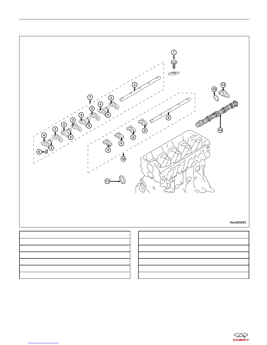
1 - Rocker Shaft Retaining Bolt

2 - Intake Rocker Arm Shaft

3 - Rocker Arm

4 - Rocker Arm

5 - Rocker Shaft Spring

6 - Hydraulic Adjuster

7 - Rocker Arm and Rocker Shaft

8 - Exhaust Rocker Arm Shaft

9 - Rocker Arm

10 - Rocker Arm and Rocker Shaft

11 - Camshaft Oil Seal

12 - O-Ring

13 - Camshaft Thrust Plate

14 - Camshaft

CYLINDER HEAD UNIT REPAIR

LTSM020081


Camshaft

• Measure the camshaft cam lobe height.

• If wear is beyond the limit, replace the camshaft.

CAMSHAFT LOBE HEIGHT

DESCRIPTION

STANDARD LOBE HEIGHT

MINIMUM LOBE HEIGHT

Intake Cam Lobe Height

37.5 mm

37 mm

Exhaust Cam Lobe Height

36.99 mm

36.49 mm

Hydraulic Adjusters

CAUTION:
The hydraulic adjusters are a precision part. There should not be any dust or foreign matter on its
surface. Do not disassemble the hydraulic adjusters. It is required to use clean diesel oil to clean
the hydraulic adjusters.

• Soak the hydraulic adjusters in clean diesel oil.

• Using special tool MD-998442 (1) and MD-998441 (2), press the steel ball on the inside of the hydraulic

adjuster and remove all air by moving the plunger
up and down 4-5 times.

NOTE :
Use the special tool and check whether the plunger can
be pressed. If it is hard to press the plunger, the
hydraulic adjuster is normal. If it is easy to press the
plunger, repeat the previous procedure and then check
the hydraulic adjuster again. If the plunger is still loose,
the hydraulic adjuster should be replaced.

CAUTION:
After the hydraulic adjuster has been prepared, it should be kept erect to avoid the loss of diesel
oil.

CYLINDER HEAD UNIT REPAIR

BESM020037

LTSM020088

02


• Using special tool MD-998440 (1) (return leakage tester), install the hydraulic adjuster.

• After the plunger has moved slightly (0.2 - 0.5

mm), measure the time it takes to move an addi-
tional 1.0 mm. If the measurement value is not
within specifications, replace the hydraulic adjuster-
.Standard Value: 4 - 20 seconds/1 mm (applying
diesel oil of 15-20°C)

Rocker Arms

• Inspect the surface of the roller (2) on all rocker

arms. If there is any damage, the rocker arm
should be replaced.

• Inspect the roller for smooth operation. If the roller

does not revolve smoothly or is loose, the rocker
arm should be replaced.

• Inspect the internal diameter (1) of the rocker arms.

If there is any damage, the rocker arm should be
replaced.

Valve & Valve Guides

Specifications

Valve & Valve Guide Specifications

DESCRIPTION

SPECIFICATION

LIMIT

Intake Valve Deflection

0.02 mm

0.02 mm

Exhaust Valve Deflection

0.04 mm

0.04 mm

Intake Valve Clearance

0.020 - 0.050 mm

0.10 mm

Exhaust Valve Clearance

0.030 - 0.070 mm

0.15 mm

Intake Valve Edge Thickness

1.0 mm

0.5 mm

Exhaust Valve Edge Thickness

1.2 mm

0.7 mm

Intake Valve Height

112.30 mm

111.80 mm

Exhaust Valve Height

114.11 mm

113.61 mm

Intake Valve Guide Height

49.30 mm

49.80 mm

Exhaust Valve Guide Height

49.30 mm

49.80 mm

CYLINDER HEAD UNIT REPAIR

LTSM020159

LTSM020037


Disassembly

NOTE :
The following special tools are required to perform the repair procedure:
• MD-998772 - Valve Spring Compressor

1 - Cylinder Head Bolt

2 - Valve Spring Keepers

3 - Upper Valve Spring Retainer

4 - Valve Spring

5 - Valve Oil Seal

6 - Lower Valve Spring Retainer

7 - Valve Guide

8 - Valve Seat

9 - Valve

10 - Cylinder Head

CYLINDER HEAD UNIT REPAIR

LTSM020090

02


Content   ..  67  68  69  70   ..