Chery Tiggo. Manual - part 68


  Index      Chery     Chery Tiggo - service repair manual 2009 year


Search            


Content   ..  66  67  68  69   ..


Chery Tiggo. Manual - part 68


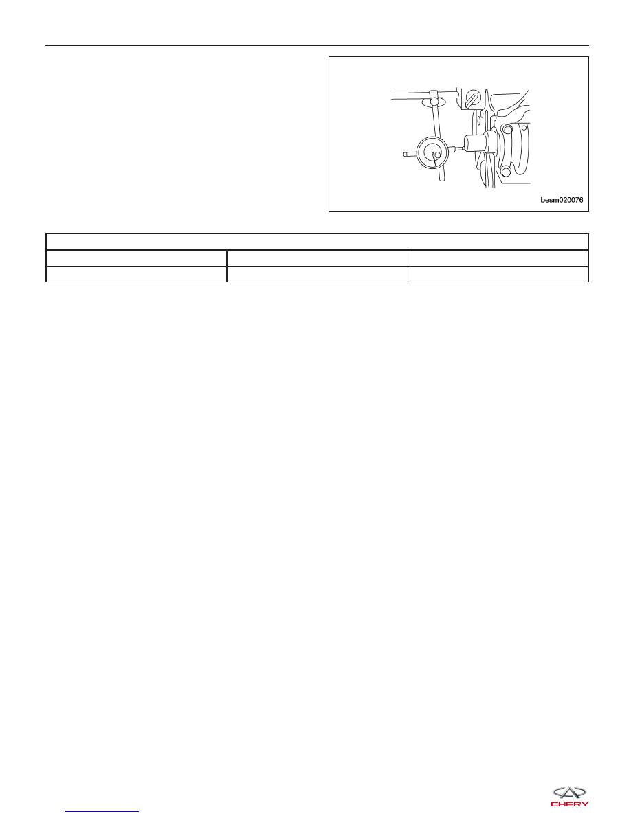
• Inspect the crankshaft axial clearance.

− If the crankshaft axial clearance exceeds the

maximum limit, replace the No.3 crankshaft
thrust bearing.

CRANKSHAFT AXIAL CLEARANCE

DESCRIPTION

SPECIFICATION

MAXIMUM LIMIT

Crankshaft

0.05 - 0.18 mm

0.25 mm

ENGINE UNIT REPAIR

BESM020076


CYLINDER HEAD UNIT REPAIR

Cylinder Head

Specifications

Torque Specifications

DESCRIPTION

TORQUE (N·m)

Cylinder Head Bolts

1st Step: Tighten the bolt to 78 N·m

2nd Step: Completely loosen the bolt

3rd Step: Retighten the bolt to 20 N·m

4th Step: Tighten the bolt an additional 90°

5th Step: Finish tightening the bolt an additional 90°

Cylinder Head Cover Bolts

11 N·m

Clearance Specifications

DESCRIPTION

SPECIFICATION (mm)

Cylinder Head Flatness

0.03

Intake Valve Deflection

0.02

Exhaust Valve Deflection

0.04

Spring Height

51

Disassembly

NOTE :
The following special tools are required to perform the repair procedure:

• MD-998772 - Valve Spring Compressor

• MD-998774 - Valve Oil Seal Installer

NOTE :
Replacement cylinder head comes complete with valves, seals, springs, retainers, keepers, tappets, and camshafts.

1. Remove camshaft.

2. Using the special tool MD-998772 (1), compress

the valve spring.

3. Remove the valve keeper, valve spring retainer

and valve spring.

4. Push the valve stem from the cylinder head and

remove the valve.

LTSM020092

02


5. Using special tool CH-20013 (1), Remove the valve

oil seal.

6. Remove the valve guide.

7. Remove the spark plugs.

Inspection

• Cylinder head must be flat within 0.03 mm.

• Inspect camshaft bearing journals for scoring.

• Remove carbon and varnish deposits from inside of

valve guides with a valve guide cleaner.

• Check the valve guide height.

Assembly

1. Install new valve guide if necessary.

2. Install new valve seat if necessary.

3. Using special tool MD-998774 (1), install the new

valve oil seal.

4. Install the valves into the cylinder head (larger diameter on intake side).

5. Install the valve springs.

6. Install the valve spring retainers.

CYLINDER HEAD UNIT REPAIR

LTSM020225

BESM020068

LTSM020094


7. Using valve spring compressor MD-998772 (1),

compress the valve springs.

8. Install the valve keepers.

9. Strike the valve stem lightly with a plastic hammer

after installation to verify proper assembly.

Camshaft

Specifications

Camshaft Specifications

DESCRIPTION

SPECIFICATION

MINIMUM LIMIT

Intake Cam Lobe Height

37.5 mm

37 mm

Exhaust Cam Lobe Height

36.99 mm

36.49 mm

CYLINDER HEAD UNIT REPAIR

LTSM020092

02


Content   ..  66  67  68  69   ..