Chery Tiggo. Manual - part 58


  Index      Chery     Chery Tiggo - service repair manual 2009 year


Search            


Content   ..  56  57  58  59   ..


Chery Tiggo. Manual - part 58


Exhaust Manifold

Removal & Installation

1. Remove the bolts attaching the exhaust manifold heat shield.

(Tighten: Exhaust manifold heat shield bolts to 14 N·m)

2. Remove the exhaust manifold heat shield.

3. Remove the three bolts securing the exhaust manifold to the catalytic converter assembly.

(Tighten: Exhaust manifold to catalytic converter bolts to 49 ± 5 N·m)

4. Disconnect the catalytic converter assembly from the manifold.

5. Remove the exhaust manifold nuts.

(Tighten: Exhaust manifold nuts to 29 ± 3 N·m)

6. Remove the exhaust manifold from the cylinder head.

7. Remove and discard exhaust manifold gasket.

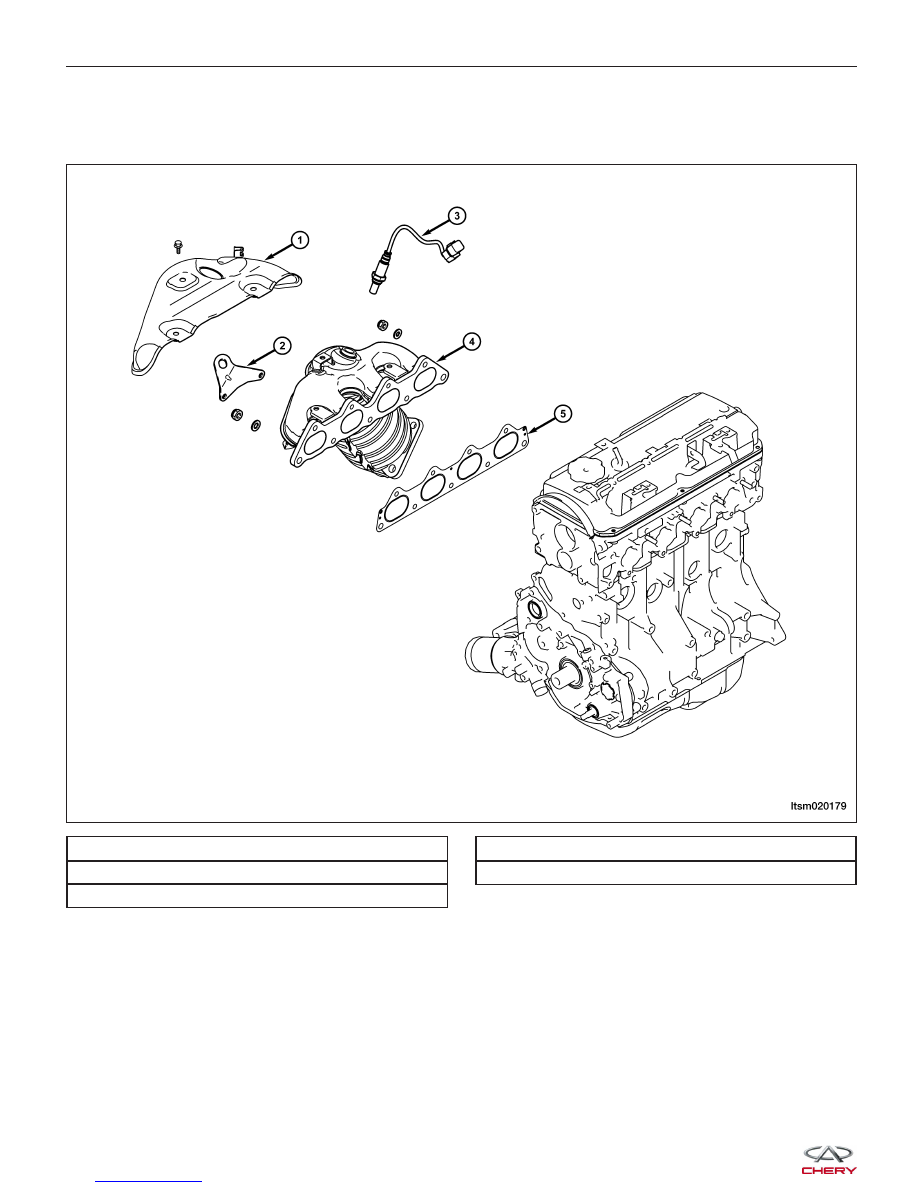
1 - Exhaust Manifold Heat Shield

2 - Engine Hanger

3 - Oxygen Sensor

4 - Exhaust Manifold

5 - Exhaust Manifold Gasket

ON-VEHICLE SERVICE

LTSM020179


8. Installation is in the reverse order of removal.

Installation Notes:
• Clean all surfaces of manifold and cylinder head.

• Install a new exhaust manifold gasket during installation.

Intake Manifold

Removal & Installation

1. Disconnect the negative battery cable.

1 - Inlet Manifold Gasket

2 - Knock Sensor

3 - Coolant Hose

4 - Coolant Hose

5 - Coolant Temperature Sensor

6 - Coolant Outlet Fitting

7 - Intake Manifold Support Bracket

8 - Intake Manifold

9 - Engine Hanger

ON-VEHICLE SERVICE

LTSM020178

02


2. Remove the accelerator cable retaining bolt from the intake manifold.

(Tighten: Accelerator cable retaining bolt to 10 N·m)

3. Remove the PCV hose (1).

4. Disconnect the four fuel injector electrical connec-

tors (1).

5. Loosen the clamp between the air intake hose and the air cleaner.

6. Loosen the clamp between the air intake hose and the throttle body and then remove the intake pipe.

7. Remove the fuel rail bracket bolts.

(Tighten: Fuel rail bracket bolts to 11 N·m)

8. Remove the fuel rail with the fuel injectors and set aside.

9. Remove the fuel injector O-rings.

10. Remove the screws securing the vacuum valve bracket to the intake manifold.

11. Set aside the vacuum valve and pipe.

12. Disconnect the intake manifold electrical harness, and vacuum hose.

ON-VEHICLE SERVICE

LTSM030024

LTSM020173


13. Remove the intake manifold bracket bolts (1).

(Tighten:

Intake

manifold

bracket

bolts

to

14 ± 1 N·m)

14. Remove the intake manifold retaining nuts.

(Tighten: Intake manifold retaining nuts to 49 ± 5 N·m)

15. Remove the intake manifold from the cylinder head.

16. Remove and discard the intake manifold gasket.

17. Installation is in the reverse order of removal.

Installation Notes:
• Clean all surfaces of the manifold and cylinder head.

• Install a new intake manifold gasket during installation.

• Install new O-rings on the fuel injectors.

ON-VEHICLE SERVICE

LTSM020154

02


Content   ..  56  57  58  59   ..