Chery Tiggo. Manual - part 54


  Index      Chery     Chery Tiggo - service repair manual 2009 year


Search            


Content   ..  52  53  54  55   ..


Chery Tiggo. Manual - part 54


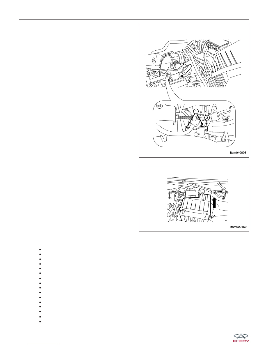
10. Disconnect and remove the fuel line (2) at the fuel

rail.

11. Remove the fuel pressure regulator retaining bolt

(1) and set the fuel pressure regulator aside.
(Tighten: Fuel pressure regulator bolt to 9 N·m)

12. Remove the air inlet hose and the air cleaner case

assembly.

13. Remove the accelerator cable bolt from the cylinder head.

14. Disconnect and remove the following electrical connectors:

Coolant temperature sensor
Crankshaft position sensor
Camshaft position sensor
Ignition coil
Four fuel injectors
Air flow sensor
Canister solenoid valve
EGR control solenoid valve
Throttle position sensor
A/C compressor
Oil pressure sensor
Power steering pump pressure switch
Generator
Upstream oxygen sensor
Knock sensor
Idle air control motor

ON-VEHICLE SERVICE

LTSM040006

LTSM020160


15. Remove the pipe from the canister control valve.

16. Disconnect the heater hoses (1) on the vehicle.

17. Remove the vacuum line from the brake booster.

18. Remove the dipstick.

19. Remove the accessory drive belt (See Accessory Drive Belt Removal & Installation in Section 02 Engine).

20. Remove the A/C compressor high and low pres-

sure pipe bolts (1) & (2).

ON-VEHICLE SERVICE

LTSM130010

LTSM130008

02


21. Disconnect the following automatic transaxle elec-

trical connectors:

• Output shaft sensor (1)

• Input shaft sensor (2)

• Electromagnetic valve switch connector (3)

• Gear switch connector (5)

22. Disconnect the transaxle fluid lines (6) using a suit-

able tool.

23. Remove the shift cable (4) from the transaxle

assembly.

24. Remove the catalytic converter to exhaust manifold

bolts (1).
(Tighten: Exhaust manifold bolt to 49 ± 5 N·m)

25. Remove the front axle shaft (See Front Axle Shaft Removal & Installation in Section 09 Driveline & Axle).

26. Raise and support the vehicle.

27. Drain the engine oil.

28. Remove the power steering pump fluid line and set aside (See Power steering pump Removal & Installation in

Section 11 Steering).

29. Lower the vehicle and install engine lift chain hangers.

ON-VEHICLE SERVICE

LTSM080153

LTSM020189


30. Remove the bolts (1) securing the front engine

mount.
(Tighten: Engine front mount bolt to 60 N·m)

31. Remove the bolts (2) securing the rear engine

mount and the bolts (1) securing the mount
bracket.
(Tighten: Engine rear mount bolt to 60 N·m)

32. Remove the bolts (2) securing the left transaxle

mount and the bolts (1) securing the mount
bracket.
(Tighten: Left transaxle mount bolt to 70 N·m)

ON-VEHICLE SERVICE

BESM080035

LTSM020188

LTSM020156

02


Content   ..  52  53  54  55   ..