Chery Tiggo. Manual - part 49
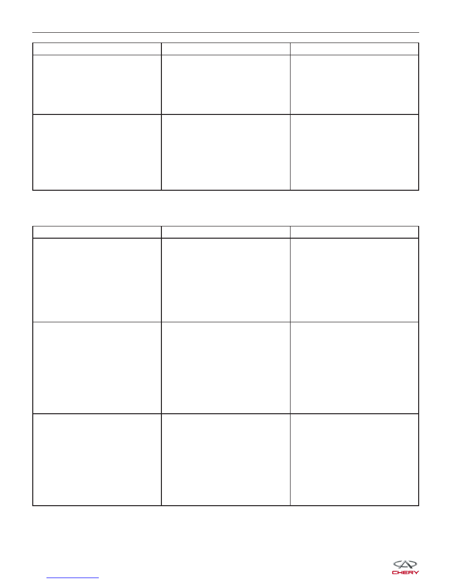
CONDITION
POSSIBLE CAUSES
CORRECTION
Engine Miss On Acceleration
1. Dirty or incorrectly gapped spark
plugs.
2. Contamination in fuel system.
7. Burned, warped, excessive
clearance, or pitted valves.
4. Faulty ignition coil(s).
1. Clean spark plugs and set gap.
2. Clean fuel system and replace
fuel filter.
3. Replace valves.
4. Test and replace if necessary.
(Refer to Appropriate Diagnostic
Information)
Engine Miss At High Speed
1. Dirty or incorrect spark plug gap.
2. Faulty ignition coil(s).
3. Dirty fuel injector(s).
4. Contamination in fuel system.
1. Clean spark plugs and set gap.
2. Test and replace if necessary.
(Refer to Appropriate Diagnostic
Information)
3. Test and replace if necessary.
(Refer to Appropriate Diagnostic
Information)
4. Clean system and replace fuel
filter.
Engine Mechanical Diagnostics
CONDITION
POSSIBLE CAUSES
CORRECTION
Valve Train Noise
1. High or low oil level in crankcase.
2. Thin or diluted oil.
3. Thick oil.
4. Low oil pressure.
5. Worn cam lobe.
6. Worn valve guides.
7. Excessive runout of valve seats
on valve faces.
1. Check and correct engine oil
level.
2. Change oil to correct viscosity.
3. Change engine oil and filter.
4. Check and correct engine oil
level.
5. Install new camshaft.
6. Replace cylinder head.
7. Grind valve seats and replace
valves.
Connecting Rod Noise
1. Insufficient oil supply.
2. Low oil pressure.
3. Thin or diluted oil.
4. Excessive bearing clearance.
5. Connecting rod journal out-of-
round.
6. Connecting rod out-of-round.
7. Misaligned connecting rods.
8. Connecting rod nuts loose.
1. Check engine oil level.
2. Check engine oil level. Inspect oil
pump relief valve and spring.
3. Change oil to correct viscosity.
4. Measure bearings for correct
clearance. Repair if necessary.
5. Replace crankshaft or grind
surface.
6. Replace connecting rod.
7. Replace bent connecting rods.
8. Tighten the connecting rod nuts.
Main Bearing Noise
1. Insufficient oil supply.
2. Low oil pressure.
3. Thin or diluted oil.
4. Excessive bearing clearance.
5. Excessive end play.
6. Crankshaft journal out-of-round or
worn.
7. Loose flywheel or torque
converter.
1. Check engine oil level.
2. Check engine oil level. Inspect oil
pump.
3. Change oil to correct viscosity.
4. Measure bearings for correct
clearance. Repair if necessary.
5. Check thrust bearing for wear on
flanges.
6. Replace crankshaft or grind
journals.
7. Tighten to correct torque.
DIAGNOSIS & TESTING