Chery Tiggo. Manual - part 40


  Index      Chery     Chery Tiggo - service repair manual 2009 year


Search            


Content   ..  38  39  40  41   ..


Chery Tiggo. Manual - part 40


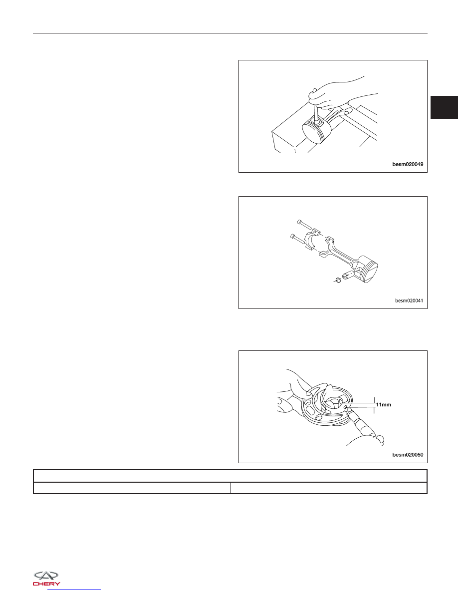
• Piston Pin Removal

− Push out the piston pin with a suitable tool.

• Connecting Rod & Piston Disassembly

− Remove the piston from the connecting rod.

Inspection

• Check the piston diameter.

PISTON DIAMETER

All Pistons

83.451 - 83.469 mm

ENGINE UNIT REPAIR

BESM020049

BESM020041

BESM020050

02


• Check the inner diameter of each cylinder bore (See Cylinder Bore Inspection in Section 02 Engine).

CYLINDER BORE

All Cylinders

83.500 - 83.510 mm

• Check piston ring to groove side clearance.

− Clean the ring slot using a suitable tool.
− Measure piston ring to groove side clearance.

RING GROOVE CLEARANCE

First Ring

0.04 - 0.08 mm

Second Ring

0.01 - 0.0251 mm

• Wipe the cylinder bore clean. Insert ring and push down with piston to ensure it is square in the bore. The ring

gap measurement must be made with the ring posi-
tioned at least 13 mm from bottom of cylinder bore
and below the bottom of the oil ring travel where
the cylinder bore has minimal wear. Check gap with
feeler gauge.

ENGINE UNIT REPAIR

BESM020063

BESM020051

BESM020052


RING END GAP CLEARANCE

First Ring

0.2 - 0.4 mm

0.8 mm

Second Ring

0.4 - 0.6 mm

1.0 mm

• Check the diameter of the piston pin bore.

• Check the outer diameter of the piston pin.

• Check the inner diameter of connecting rod (small end).

PISTON PIN CLEARANCE

Piston and Piston Pin

0.002 - 0.013 mm

Assembly

1. Install the piston to the connecting rod. Assemble the components in their original positions.

2. Using a piston ring expander, install the piston rings. Assemble the components in their original positions.

3. Assemble all components in the reverse order of disassembly.

ENGINE UNIT REPAIR

BESM020053

BESM020054

02


Connecting Rods

Specifications

Torque Specifications

DESCRIPTION

TORQUE (N·m)

Connecting Rod Bolts

1st Step: Tighten bolts to 25 N·m

2nd Step: Tighten the connecting rod bolts an additional

90°

Clearance Specifications

DESCRIPTION

SPECIFICATION (mm)

Connecting Rod Radial Clearance

0.016 - 0.051

Connecting Rod Axial Clearance

0.002 - 0.013

Disassembly

1. Remove the connecting rod cap bolts.

2. Remove the connecting rod bearing cap.

3. Using a hammer handle or similar tool, push the

piston

and

connecting

rod

assembly

(1)

out

through the cylinder head side of the engine block.

NOTE: Before removing the piston and connecting
rod assembly, check the connecting rod side
clearance.

ENGINE UNIT REPAIR

BESM020043

BESM020044


Content   ..  38  39  40  41   ..