Chery Tiggo. Manual - part 21


  Index      Chery     Chery Tiggo - service repair manual 2009 year


Search            


Content   ..  19  20  21  22   ..


Chery Tiggo. Manual - part 21


8. Installation is in the reverse order of removal.

Inspection

NOTE :
All measurements should be taken with the engine block at room temperature, 21°C.

Engine Block
• Clean cylinder block thoroughly and check all core hole plugs for evidence of leaking.

• Examine block and cylinder bores for cracks or fractures.

• Check block deck surfaces for flatness. Deck surface must be within service limit of 0.050 mm.

Cylinder Bore

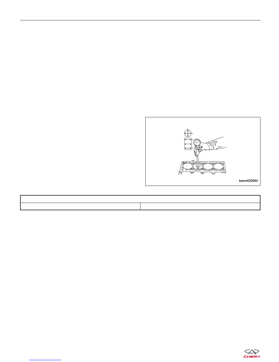
• The cylinder walls should be checked for out-of-round and taper with cylinder indicator or equivalent. If the cyl-

inder walls are badly scuffed or scored, the cylinder block should be replaced, and new pistons and rings fitted.

• Measure the cylinder bore at three levels in directions X and Y. Top measurement should be 10 mm down and

bottom measurement should be 10 mm up from
bottom of bore.

CYLINDER BORE

All Cylinders

81.000 - 81.010 mm

Assembly

NOTE :
Cleanliness is extremely important during the engine assembly procedure. Any foreign material, including any mate-
rial created while cleaning gasket surfaces, that enters the oil passages, coolant passages or the oil pan can cause
engine failure.

NOTE :
Assemble all components in their original position.

1. Install the pistons to the connecting rods.

2. Using a piston ring expander, install the piston rings.

3. Assemble all components in the reverse order of disassembly.

ENGINE UNIT REPAIR

BESM020063


Pistons

Specifications

Clearance Specifications - Pistons

DESCRIPTION

SPECIFICATION (mm)

Surface Distortion Limit

0.15

Inner Diameter Standard

81

Out-Of-Round

< 0.008

Taper

< 0.01

Clearance Specifications - Piston Ring Groove

DESCRIPTION

SPECIFICATION (mm)

First Ring

0.04 - 0.08

Second Ring

0.01 - 0.0251

Clearance Specifications - Piston Ring End Gap

DESCRIPTION

SPECIFICATION

LIMIT

First Ring End Gap

0.2 - 0.4 mm

0.8 mm

Second Ring End Gap

0.4 - 0.6 mm

1.0 mm

Clearance Specifications - Piston to Piston Pin

DESCRIPTION

SPECIFICATION (mm)

Piston To Piston Pin

0.002 - 0.013

ENGINE UNIT REPAIR

02


Disassembly

• Piston Ring Removal

− Using a suitable ring expander, remove upper

and intermediate piston rings.

− Remove the upper oil ring side rail, lower oil

ring side rail and then oil ring expander from
piston.

− Clean ring grooves of any carbon deposits.

CAUTION:
Before removing the piston rings (1), check the
piston ring side clearance. Be careful to mark
the location of the piston rings if they are to
be reused.

• Piston Pin Snap Ring Removal

− Using snap ring pliers, remove the snap ring

(1).

− Heat the pistons if necessary.

ENGINE UNIT REPAIR

BESM020047

BESM020046

BESM020048


• Piston Pin Removal

− Push out the piston pin with a suitable tool.

• Connecting Rod & Piston Disassembly

− Remove the piston from the connecting rod.

Inspection

Check the piston diameter.

PISTON DIAMETER

All Pistons

80.946 - 80.964 mm

ENGINE UNIT REPAIR

BESM020049

BESM020041

BESM020050

02


Content   ..  19  20  21  22   ..