Chery Tiggo. Manual - part 19


  Index      Chery     Chery Tiggo - service repair manual 2009 year


Search            


Content   ..  17  18  19  20   ..


Chery Tiggo. Manual - part 19


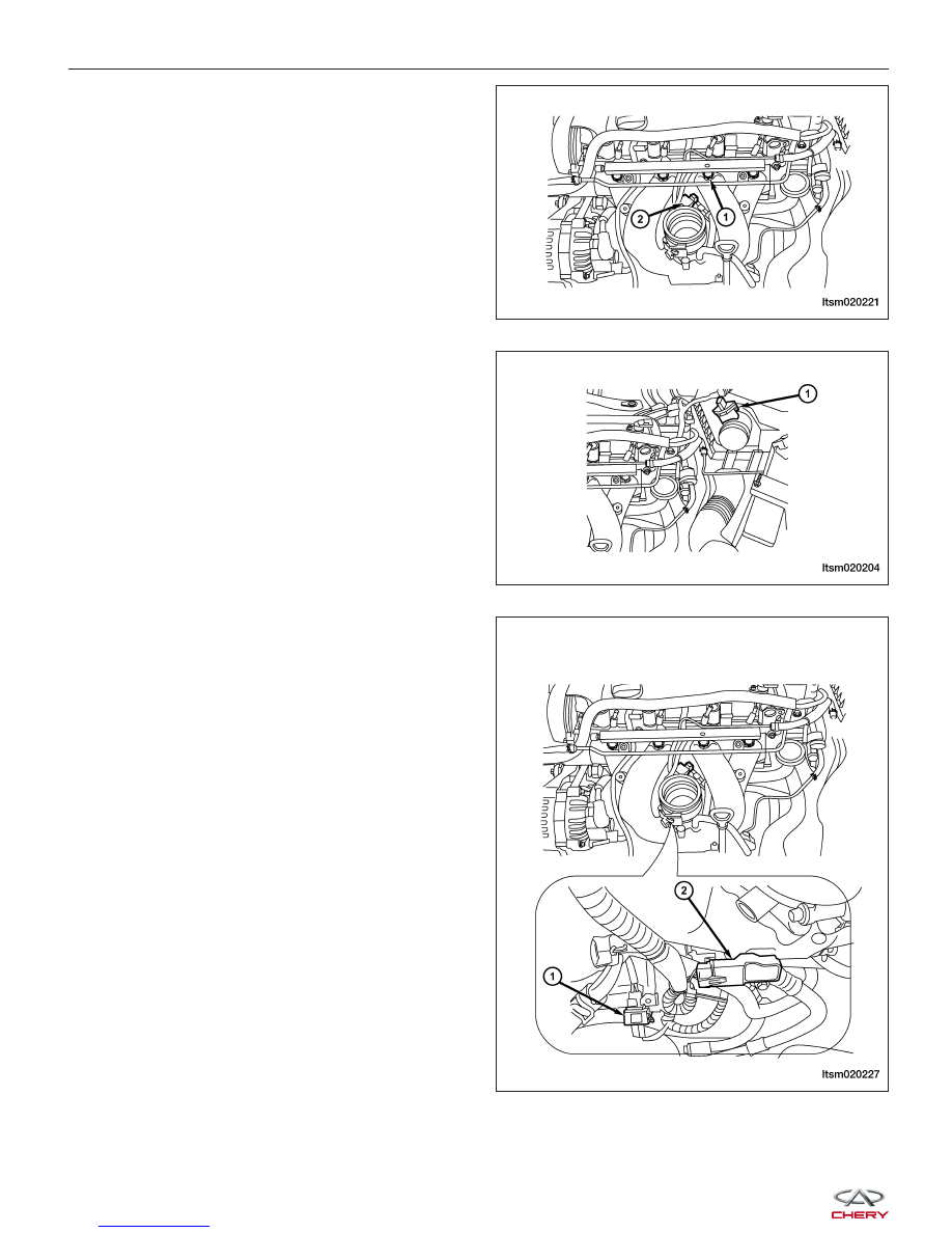
5. Disconnect the four fuel injector electrical connec-

tors (1).

6. Disconnect the throttle body control electrical con-

nector (2).

7. Disconnect the air flow sensor electrical connector

(1) (1.8L engine).

8. Disconnect the air pressure sensor electrical con-

nector (1) (1.6L engine).

9. Remove MAP sensor (2) from intake manifold.

10. Loosen the clamp between the air intake hose and the air cleaner.

11. Loosen the clamp between the air intake hose and the throttle body and then remove the intake pipe.

12. Loosen the clamp on the PCV hose and then disconnect the PCV hose.

ON-VEHICLE SERVICE

LTSM020221

LTSM020204

LTSM020227


13. Remove the fuel rail bracket bolts (1).

(Tighten: Fuel rail bracket bolts to 11 N·m)

14. Remove the fuel rail with the fuel injectors and set aside.

15. Remove the screws securing the vacuum valve bracket to the intake manifold.

16. Set aside the vacuum valve and pipe.

17. Disconnect intake manifold electrical harness, and vacuum hose.

18. Remove the bolts (2) & (3) securing the engine oil

dipstick to intake manifold. Remove the dipstick.
(Tighten: Dipstick bracket bolts to 11 N·m)

19. Disconnect the oil pressure switch connect (4).

20. Remove the nuts (1) securing the intake manifold

to cylinder head.
(Tighten: Intake manifold nuts to 11 N·m)

21. Installation is in the reverse order of removal.

Installation Notes:
• Clean all surfaces of manifold and cylinder head.

• Install a new intake manifold gasket during installation.

• Install new O-rings on the fuel injectors.

Idler Pulley

Removal & Installation

1. While using a suitable tool and securely holding the hexagonal portion of the drive belt tensioner, rotate the

pulley counterclockwise to loosen the drive belt.

WARNING!

Avoid placing hands near the drive belt tensioner while it is being held.

ON-VEHICLE SERVICE

LTSM020222

LTSM020223

02


2. Remove the drive belt.

Upper Accessory Drive Belt Idler Pulley (1)
• Remove the bolt and the upper accessory drive

belt idler pulley.

(Tighten: Upper idler pulley bolt to 45 N·m)

Lower Accessory Drive Belt Idler Pulley (2)
• Remove the bolt and the lower accessory drive belt

idler pulley.

(Tighten: Lower idler pulley bolt to 45 N·m)

3. Installation is in the reverse order of removal.

Oil Filter

Removal & Installation

NOTE :
The following special tools are required to perform the repair procedure:
• CH-10003 - Oil Filter Remover

WARNING!

Prolonged and repeated contact with engine oil will harm your skin. If engine oil is spilled on your skin, wash it
off immediately with water. In addition, used engine oil contains potentially harmful contaminants which may
cause skin cancer. Always use adequate skin protection when performing vehicle service.

CAUTION:
When servicing the oil filter, install the special tool against the base of the filter to avoid deforming
the filter.

1. Using special tool CH-10003 oil filter remover,

remove the oil filter (1).
(Tighten: Oil filter to 25 N·m)
CAUTION: When removing the oil filter, ensure
that the oil filter gasket is not stuck to the
engine. The oil filter gasket must be removed
from the engine before installing the new oil
filter.

2. Installation is in the reverse order of removal.

Installation Notes:
• Clean the surface, and verify the oil filter does not leak.

ON-VEHICLE SERVICE

LTSM020203

LTSM020206


Oil Pan

Removal & Installation

1. Remove the oil dipstick.

2. Raise and support the vehicle.

3. Remove the oil pan drain plug and drain the

engine oil.
(Tighten: Oil pan drain plug to 40 N·m)

NOTE :
Do not pry on cylinder block to remove oil pan.

4. Remove oil pan bolts (1).

(Tighten: Oil pan bolts to 18 N·m)

5. Using a putty knife, loosen seal around oil pan.

6. Remove the oil pan.

7. Installation is in the reverse order of removal.

Installation Notes:
• Oil pan sealing surfaces must be free of grease or oil.

• Install the four oil pan corner bolts in the sequence shown (1-2-3-4).

• Install the remaining oil pan bolts.

• Torque all the oil pan bolts to the proper

specification.

ON-VEHICLE SERVICE

LTSM020205

VISM020013

02


Content   ..  17  18  19  20   ..