Chery Tiggo. Manual - part 20


  Index      Chery     Chery Tiggo - service repair manual 2009 year


Search            


Content   ..  18  19  20  21   ..


Chery Tiggo. Manual - part 20


Oil Pump

Removal & Installation

1. Remove the accessory drive belt (See Accessory Drive Belt Removal & Installation in Section 02 Engine).

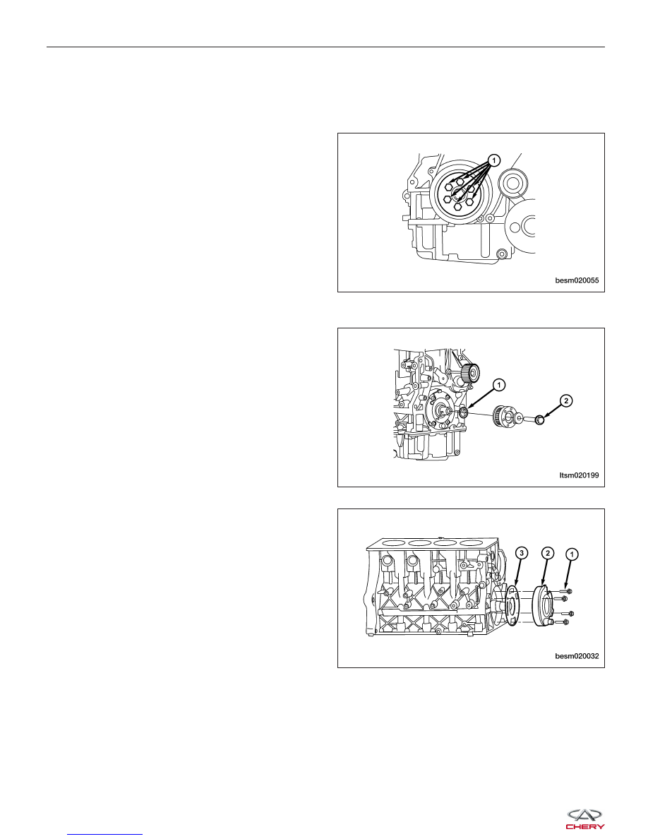
2. Remove the crankshaft vibration damper retaining

bolts (1).
(Tighten: Crankshaft vibration damper bolts to 25
N·m)

3. Remove the engine timing belt (See Engine Timing Belt Removal & Installation in Section 02 Engine).

4. Remove the crankshaft timing belt pulley bolt (2)

from the crankshaft.
(Tighten: Crankshaft timing belt pulley bolt to 130
N·m and an additional 65°)

5. Remove the key-way from the crankshaft.

6. Using an appropriate tool, remove the front crank-

shaft oil seal (1).

7. Remove the four oil pump bolts (1).

(Tighten: Oil pump bolts to 11 N·m)

8. Remove the oil pump (2) using a suitable tool.

9. Remove the oil pump gasket (3).

10. Installation is in the reverse order of removal.

Installation Notes:
• Before installing, prime the new oil pump. Fill the oil pump with engine oil and rotate the oil pump.

• Replace the oil pump gasket.

ON-VEHICLE SERVICE

BESM020055

LTSM020199

BESM020032


Oil Strainer

Removal & Installation

1. Raise and support the vehicle.

2. Remove the oil pan (See Oil Pan Removal & Installation in Section 02 Engine).

3. Remove the oil strainer retaining bolts (1).

(Tighten: Oil strainer bolts to 18 N·m)

4. Carefully remove the oil strainer.

5. Installation is in the reverse order of removal.

Installation Notes:
• Install new O-rings on the oil strainer pipe.

ON-VEHICLE SERVICE

BESM020018

02


ENGINE UNIT REPAIR

Engine Block

Specifications

Torque Specifications

DESCRIPTION

TORQUE (N·m)

Connecting Rod Cap Bolts

1st Step: Tighten the bolt to 25 N·m

2nd Step: Tighten the bolt an additional 90°

Main Bearing Cap Bolts

1st Step: Tighten the bolt to 45 N·m

2nd Step: Tighten the bolt an additional 180°

Lower Cylinder Block Bolts

23

Clearance Specifications

DESCRIPTION

SPECIFICATION (mm)

Surface Distortion Limit

0.15

Inner Diameter Standard

81

Out-Of-Round

< 0.008

Taper

< 0.01

Disassembly

1. Remove the oil pan and then remove oil baffle.

2. Remove the oil strainer.

3. For each connecting rod/piston assembly to be removed, rotate the crankshaft to the bottom dead center position

for each cylinder.

NOTE :
Before removing the connecting rod/piston assembly, check the connecting rod side clearance.

BESM020060


4. Remove the connecting rod retaining bolts.

5. Remove the connecting rod bearing cap.

6. Using a hammer handle or similar tool, push the

connecting rod/piston assembly (1) out through the
top of the cylinder block.

7. Remove the connecting rod bearings (See Con-

necting Rod Removal & Installation in Section 02
Engine).

CAUTION: When removing the connecting rod side bearings, note the installation position. Keep them in
the correct order.

ENGINE UNIT REPAIR

BESM020042

BESM020043

BESM020044

BESM020045

02


Content   ..  18  19  20  21   ..