Chery Tiggo. Manual - part 17


  Index      Chery     Chery Tiggo - service repair manual 2009 year


Search            


Content   ..  15  16  17  18   ..


Chery Tiggo. Manual - part 17


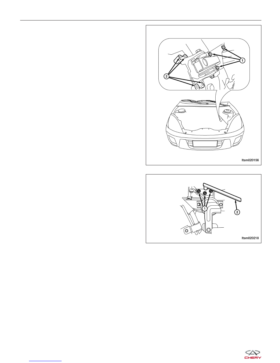
33. Remove the left transaxle mount bolts (2) and the

transaxle mount bracket retaining bolts (1).
(Tighten: Left transaxle mount bolt to 70 N·m)

34. Using special tool CH-20001 (2), remove the three

bolts (1) securing the right engine mount.
(Tighten: Engine right mount bolt to 70 N·m)

35. Verify all components between the engine and vehicle are disconnected.

36. Remove the front sub-frame (See Front Sub-Frame Removal & Installation in Section 10 Suspension).

37. Hoist the engine from vehicle.

CAUTION:
Verify all electrical connectors are disconnected prior to engine/transaxle removal.

38. Separate the engine and transaxle.

ON-VEHICLE SERVICE

LTSM020156

LTSM020218


39. Remove the accessory drive belt (1) (See Acces-

sory Drive Belt Removal & Installation in Section
02 Engine).

40. Remove the generator (1) from the bracket (See

Generator Removal & Installation in Section 05
Starting & Charging).

41. Remove the A/C compressor pipe.

42. Remove the A/C compressor (2) (See A/C Com-

pressor Removal & Installation in Section 13 Heat-
ing & Air Conditioning).

43. Remove the power steering pump (1) with the pip-

ing connected and set the pump aside. Secure the
pump with wire.

44. Installation is in the reverse order of removal.

ON-VEHICLE SERVICE

LTSM020200

BESM020029

BESM020028

02


Engine Timing Belt

Removal & Installation

NOTE :
The following special tools are required to perform the repair procedure:
• CH-20001 - Right Engine Mount Bolt Remover

• CH-20003 - Crankshaft Holder

• CH-20010 - Camshaft Holder

• Engine Hoist

1. Release the coolant system pressure.

WARNING!

Always allow the engine to cool before opening the cooling system. Do not loosen the coolant pressure relief
cap when the engine is operating or the cooling system is hot. The cooling system is under pressure; steam and
hot liquid can come out forcefully when the cap is loosened slightly. Failure to follow these instructions may
result in serious personal injury.

1 - Timing Belt Upper Cover Bolt

2 - Timing Belt Upper Cover

3 - Timing Belt Cover Gasket

4 - Timing Belt

5 - Timing Belt Touch Pulley

6 - Camshaft Bolt

7 - Camshaft

8 - Rear Timing Cover Bolt

9 - Rear Timing Cover

10 - Idler Pulley

11 - Tensioner Pulley

12 - Tensioner Pulley Bolt

13 - Timing Belt Lower Cover

14 - Timing Belt Lower Cover Bolt

15 - Timing Belt Upper Cover Bolt

ON-VEHICLE SERVICE

LTSM020162


2. Remove the coolant reservoir (1) and set aside.

3. Attach an engine hoist and support the engine using an engine hoist.

4. Using special tool CH-20001 (2), remove the

engine right mount bolts (1) and bracket.
(Tighten: Engine right mount bolts to 70 N·m)

5. Remove the accessory drive belt (See Accessory Drive Belt Removal & Installation in Section 02 Engine).

6. Remove the crankshaft vibration damper bolts (1).

(Tighten: Crankshaft vibration damper bolts to
25 N·m)

ON-VEHICLE SERVICE

LTSM020190

LTSM020218

BESM020055

02


Content   ..  15  16  17  18   ..