Chery Tiggo. Manual - part 15


  Index      Chery     Chery Tiggo - service repair manual 2009 year


Search            


Content   ..  13  14  15  16   ..


Chery Tiggo. Manual - part 15


5. Remove the rear oil seal using a suitable tool.

6. Installation is in the reverse order of removal.

Installation Notes:
• When installing seal, lubricate seal guide with clean

engine oil.

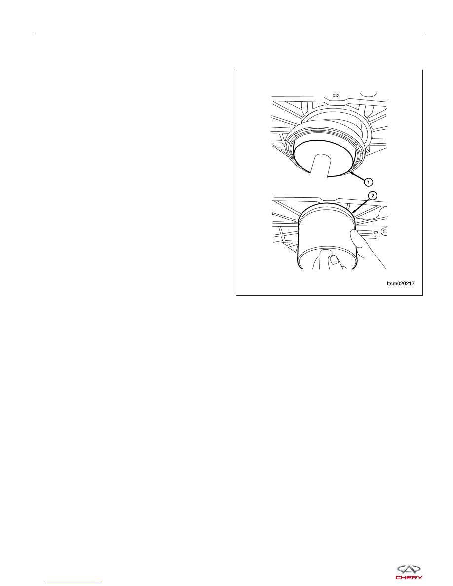
• Position the seal over the rear crankshaft seal

guide.

• Use special tool CH-20005 (2) CH-20006 (1), to

install the rear crankshaft oil seal.

• Ensure that the lip of the seal is facing toward the

crankcase during installation.

ON-VEHICLE SERVICE

LTSM020217


Engine Mounts

Removal & Installation - Left Mount

NOTE :
The following special tools are required to perform the repair procedure:
• Engine Hoist

1. Disconnect the negative battery cable.

2. Support the engine with the engine hoist.

3. Remove the air cleaner housing (See Air Cleaner

Housing Removal & Installation in Section 02
Engine).

4. Remove the air cleaner housing base tray.

5. Remove the engine left mount retaining bolts (2)

and remove the engine left mount bracket bolts (1).
(Tighten: Engine left mount bolts to 70 N·m)

6. Installation is in the reverse order of removal.

ON-VEHICLE SERVICE

LTSM020156

02


Removal & Installation - Right Mount

NOTE :
The following special tools are required to perform the repair procedure:
• Engine Hoist

1. Disconnect the negative battery cable.

2. Support the engine with the engine hoist.

3. Remove the engine right mount retaining bolts (2)

and remove the engine right mount bracket bolts
(1).
(Tighten: Engine right mount bolts to 70 N·m)

4. Installation is in the reverse order of removal.

Removal & Installation - Front Mount

NOTE :
The following special tools are required to perform the
repair procedure:
• Engine Hoist

1. Disconnect the negative battery cable.

2. Support the engine with the engine hoist.

3. Remove the bolts (1) securing the front engine

mount.
(Tighten: Engine front mount bolts to 60 N·m)

4. Installation is in the reverse order of removal.

ON-VEHICLE SERVICE

LTSM020155

BESM080035


Removal & Installation - Rear Mount

NOTE :
The following special tools are required to perform the
repair procedure:
• Engine Hoist

1. Disconnect the negative battery cable.

2. Support the engine with the engine hoist.

3. Remove the engine rear mount retaining bolts (2)

and remove the engine rear mount bracket bolts
(1).
(Tighten: Engine rear mount bolts to 60 N·m)

4. Installation is in the reverse order of removal.

Engine Assembly

Removal & Installation

NOTE :
The following special tools are required to perform the repair procedure:
• CH-20001 - Right Engine Mount Bolt Remover

• Engine Hoist

NOTE :
The engine is removed with the transaxle as an assembly.

1. Remove the vehicle hood.

2. Remove the negative battery cable from the engine.

3. Remove the engine cover.

4. Remove the battery, battery hold downs, and battery tray (See Battery Removal & Installation in Section 05

Starting & Charging).

5. Discharge air conditioning system (See A/C System Evacuation and Recharge in Section 13 Heating & Air Con-

ditioning).

6. Drain the cooling system (See Cooling System Draining and Filling in Section 06 Cooling).

WARNING!

Always allow the engine to cool before opening the cooling system. Do not loosen the coolant pressure relief
cap when the engine is operating or the cooling system is hot. The cooling system is under pressure; steam and
hot liquid can come out forcefully when the cap is loosened slightly. Failure to follow these instructions may
result in serious personal injury.

ON-VEHICLE SERVICE

LTSM020188

02


Content   ..  13  14  15  16   ..