Chery Tiggo. Manual - part 10


  Index      Chery     Chery Tiggo - service repair manual 2009 year


Search            


Content   ..  8  9  10  11   ..


Chery Tiggo. Manual - part 10


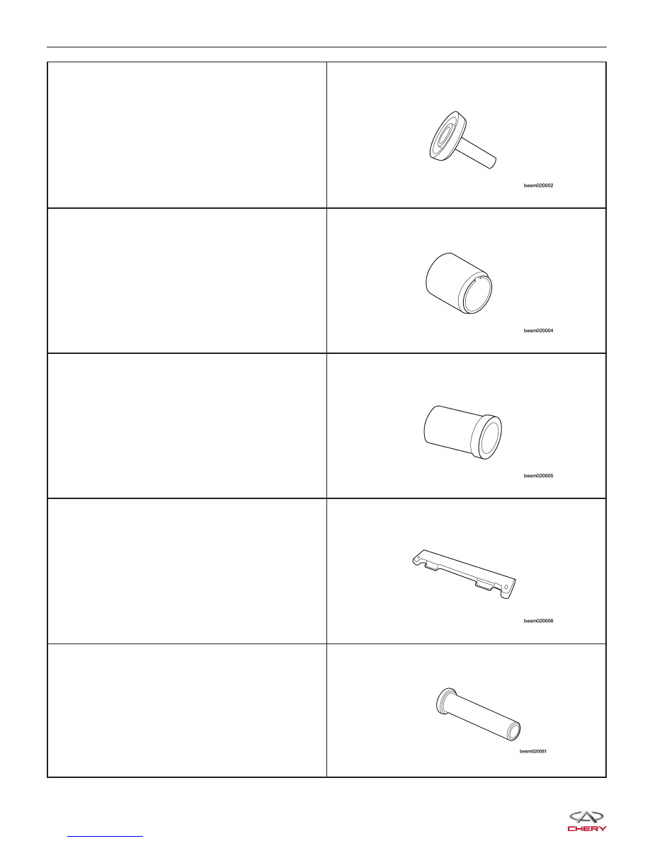
Rear Crankshaft Oil Seal Guide

CH-20006

Front Crankshaft Seal Installer

CH-20007

Front Crankshaft Seal Guide

CH-20008

Camshaft Holder

CH-20010

Valve Seal Installer

CH-20011

GENERAL INFORMATION


Valve Stem Seal Installer Guide

CH-20012

Valve Seal Remover

CH-20013

Valve Keeper Installer

CH-20017

Valve Spring Compressor

CH-20018

Crankshaft Belt Pulley Fixture

CH-20019

GENERAL INFORMATION

02


Flywheel Fixture

CH-20043

Engine Hoist

Oil Filter Remover

CH-10003

Lubrication System

The engine lubrication system operates as follows:

• Oil is drawn into the oil pump through the oil pump strainer tube in the sump of the oil pan.

• Oil is pumped through the oil filter on the cylinder block.

• Oil enters the main oil gallery where it is distributed to the crankshaft main journals and to the cylinder head.

• From the main journals, the oil is routed through cross-drilled passages in the crankshaft to lubricate the con-

necting rod bearings. Controlled leakage through the crankshaft main bearings and connecting rod bearings is
slung radially outward to cool and lubricate the cylinder walls as well as the entire connecting rod, piston and
piston ring assembly.

• The engine lubrication system is a full-flow filtration, pressure feed type. The oil pump body is mounted to the

engine block. The pump inner rotor is driven by the crankshaft.

Engine Oil Pressure Specifications

Lower Idle Speed (800 ± 50 RPM)

1.2 - 1.5 bar

High Idle Speed (2000 RPM)

3.2 - 3.5 bar

High Speed (4000 RPM)

3.7 ± 0.5 bar

GENERAL INFORMATION


Engine Lubrication System Exploded View

1 - Oil Dipstick

2 - Oil Dipstick Bolt

3 - Oil Dipstick Bracket

4 - Oil Dipstick Guide

5 - Crankshaft Rear Oil Seal

6 - O-Ring

7 - Oil Filter Bracket Gasket

8 - Oil Filter Bracket

9 - Pressure-Relief Plunger

10 - Flange Bolt

11 - Flange Bolt

12 - Oil Cooler

13 - Oil Filter Connector

14 - Oil Filter

15 - Dowel Pin

16 - Oil Pan Bolt

17 - Oil Pan Bolt

18 - Oil Pan Bolt

19 - Oil Pan

20 - O-Ring

21 - O-Ring

22 - Oil Pump Strainer Bolt

23 - Oil Pump Strainer

24 - Baffle Plate

25 - O-Ring

26 - O-Ring

27 - Crankshaft Front Oil Seal

28 - Oil Pump Bolt

29 - Oil Pump Assembly

30 - Oil Pump Assembly Gasket

GENERAL INFORMATION

LTSM020161

02


Content   ..  8  9  10  11   ..