Chery SQR 7160 sedan. Manual - part 64


  Index      Chery     Chery SQR 7160 sedan - service repair manual


Search            


Content   ..  62  63  64  65   ..


Chery SQR 7160 sedan. Manual - part 64


The manual of 4HP14    A/T removing and installing                                                        CHERY AUTOMOBILE CO., LTD 

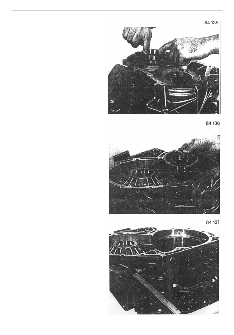
Preheat to 70℃, and press bearing outer race 09 

090 and 09 040 into the housing. 


Install driven bearing outer race properly, and 

adjust its position in the housing. Otherwise the 

mounting bolt can not be aligned with threaded 

holes.   


Install two bearing outer race mounting bolts 09 

100, and replace the sealing washer 09 104 with 

new one.   

Tool: 45#


socket spanner 

Torque: 20Nm   


-66- 

The manual of 4HP14 A/T removing & installing                                                                CHERY AUTOMOBILE CO., LTD 

Press differential oil sealing 09 130 into location   

with installing sleeve 5×46 000 299.     


Install shift shaft oil sealing 06 010 with special 

spindle drift 5×46 000 187. 


Knock rolling pin 06 030 into pawl spring 06 020 

with a plastic hammer. 


-67-

The manual of 4HP14    A/T removing and installing                                                        CHERY AUTOMOBILE CO., LTD 

Insert brake rotor dowel pin 06 100 and adjusting 

piece 5P 89 001 995.     


Install pawl spring dowel pin 06 040, and then 

install the pawl spring. 


Keep pawl spring close to the adjusting piece, 

and then fix with two bolts 06 050. 

Tool: 27# inner socket spanner 

Torque: 10Nm 


Insert shift shaft 06 060 half or so, then install 

shift cam 06 070 into shift shaft, and assemble 

shift shaft to stop. 


-68- 

The manual of 4HP14 A/T removing & installing                                                                CHERY AUTOMOBILE CO., LTD 

  Connect locking cam 24 020 and brake rotor 06 

110 with the lock spring 24 010. Locking cam 

must be installed on brake rotor. 


Install the whole mechanism on the dowel pin, 

and connect the brake rotor and lock cam with 

spring.   


Shift cam and lock cam MUST BE adjusted to 

installation position. Install brake rotor and adjust 

its location as shown on figure.     


-69-


Content   ..  62  63  64  65   ..