Chery SQR 7160 sedan. Manual - part 31


  Index      Chery     Chery SQR 7160 sedan - service repair manual


Search            


Content   ..  29  30  31  32   ..


Chery SQR 7160 sedan. Manual - part 31


CAC Gasoline Engine Maintenance And Servicing Manual 

42 


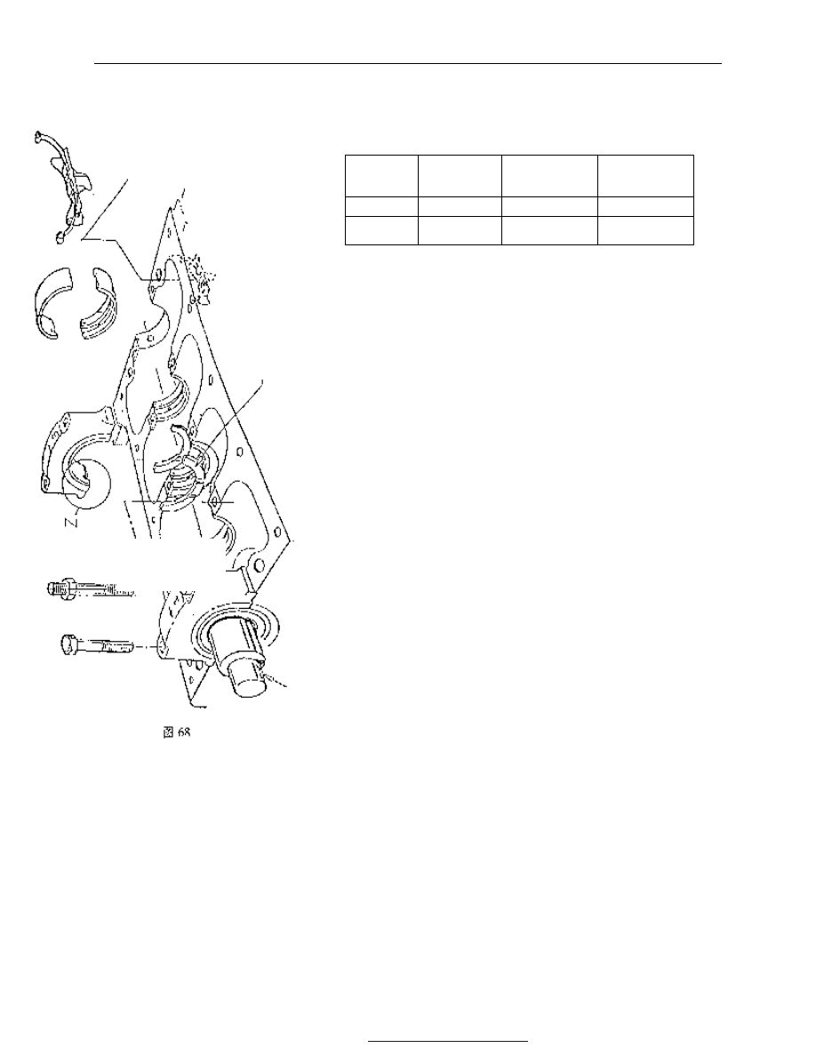
—the  size  of  crankshaft  thrust,  thrust  washer  and  cylinder  block 
thrust:                                        unit:mm 

 
Installation: 
——Before  installation,  use  the  second  screw  tap  taps  the  threaded 
hole  in  cylinder  body,  especially  the  threaded  hole  of  cylinder  head 
bolt and main bearing bolt. 

The threads of cylinder head bolt is M10×1.5—6H,the threaded 

hole of main bearing bolt is M12×1.75—6H。 
——The installation of crankshaft woodruff key 

Drive  the  semicircular  key  into  key  groove  lightly.  The 

magnitude of interference for key and key groove is 0.00—0.051mm。
After  the  semicircular  key  is  installed,    check  the  protrusion  height. 
It should be 1.392—1.739mm. 
——Crankshaft thrust washers are two pieces. They are only installed 
on the front and back thrust surface of cylinder block.     

Before  installation,  apply  the  engine  oil  on  the  surface  with  oil 

groove  of  thrust  washer. position  the surface with  oil  groove  towards 
the cylinder body and the surface with oil groove towards crankshaft. 
——During  installing  crankshaft,  engine  oil  should  be  applied  main 
journal, connecting rod journal, thrust surface and bearing half. 
——The character like 1,2,3,4,5 are casted on the top of main bearing 
cap and also an arrow. During assembling, install them from the front 
according to the sequence. At the same time, have the arrow pointing 
to the  front end surface  of cylinder block.  The width  of  main bearing 
cap 1,2,4,5 is same, but the width of main bearing cap 3 is larger than 
others. 

The main bearing cap is retained by rabbet. It is press fit between 

rabbet  and  cylinder  body.  The  press  fit    clearance  is 
0.025—0.145mm.  After  installation,  the  surface  of  the  first  and  the 
fifth  main  bearing  caps  should  be  even  or  lower  than  the  front  and 
back end surface of cylinder body. 

level 

The  size  of 
cylinder  body 
thrust 

The 

size 

of 

crankshaft thrust 

The  thickness  of 
thrust washer 

standard 

24±0.03 

28.825—28.875 

2.326±0.025 

oversize 
0.38 

24±0.03 

29.205—29.255 

2.516±0.025 

T

w

o

 t

h

ru

st

 p

ie

ce


Fig. 68 

PDF 文件使用 "pdfFactory Pro" 试用版本创建  


www.fineprint.com.cn

CAC Gasoline Engine Maintenance And Servicing Manual 

43 

——Nine main bearing bolts are hex head flange side bolts, and one is stud. 
For  horizontal  engine,  the  stud  is  mounted  in  the  left  threaded  hole  of  the 
second  main  bearing  cap  (see  from  the  front)  which  is  for  installing  the 
carrier of  oil collector. For the  vertical engine, it should  be  mounted  on  the 
left threaded hole of the forth main bearing cap (see from the front).   

Before installing the main bearing bolt, engine oil should be applied on 

the joint surface of head end. 

The  main  bearing  bolt  and  stud  should  be  screwed  by  hand  first  and 

tightened to 90—100Nm. 
——The max rotating torque of the crankshaft (with piston rod assembly) is 
16Nm. 
 
12】. The removal and installation of oil baffle assembly 

 
Removal: 
——Take  out  the  oil  baffle  assembly 
from  the  right  of  the  back  end  of  the 
cylinder body. 


Installation: 

——Install  the  oil  baffle  assembly  from 
the  right  of  the  back  end  of  the  cylinder 
body  (viewed  from  the  front).  The  oil 
baffle assembly should be tensioned.  The 
spring  should  be  lower  than  the  flange 
surface of cylinder block oil pan. 


Fig. 69 

PDF 文件使用 "pdfFactory Pro" 试用版本创建  


www.fineprint.com.cn

CAC Gasoline Engine Maintenance And Servicing Manual 

44 

13】. Engine oiling system: 
1). The description of the oiling system: 

 
        Through  oil  collector  (2),  the  rotary  oil  pump(1)  which  is 
installed in the front end of crankshaft draws oil from oil pan (3) 
and    pressurizes.  The  pressure  oil  comes  into  the  full  flow  type 
oil  filter  through  the  assistant  oil  passage  (4)  on  the  left  of 
cylinder  body  (viewed  from  the  front).  The  pressure  relief  valve 
(6)  is  installed  inside  the  oil  pump  case  to  control  main  oil 
passage pressure . The pressure relief valve will be opened under 
the pressure  within 440kPa±20kPa.  The filtered  oil    comes out 
from  the  center  hole  of  oil  filter  and    comes  into  the  main  oil 
passage of engine (5) through the center hole of filter connector. 
        From  the  main  oil  passage,  oil  lubricates  the  main  bearing 
through  the  bore  in  the  cylinder  body  and  lubricates  the 
connecting rod bearing through oil passage in the crankshaft. 
        There  is  a  small  oil  port  in  the  connecting  rod  bearing  bore 
near  the  exhaust  side  in  the  connecting  rod  body.  The  oil  sprays 
out from this small oil port to lubricate the piston pin and cylinder 
bore. 
        Oil  pressure  sensor  (8)  is  located  near  the  oil  filter.  It  is 
connected with the main oil passage by a inner oil passage. Oil is 
provided to the third journal of camshaft through this oil passage. 
        Other journals of camshaft are lubricated by the oil provided 
by  the  middle  oil  passage  of  camshaft.  Two  sides  of  the  middle 
oil passage are sealed by steel ball. 
                                                                                                 

Hydraulic lifter oil comes from oil gallery on cylinder head, 

which is supplied from oil channel on camshaft neck   
        The  oil  provided  by  the  oil  port  inside  the  hydraulic  valve 
lifting rod lubricates the contact face     

of valve rocker and hydraulic valve lifting rod. 

                                                                                The 

oil 

to 

lubricate  the  rocker  carrier  is  provided  by  the  oil  passage  of 
cylinder head. 

                                                                                                The 

contact  face  of  the  tip  end  of  valve  and  rocker  is  lubricated  by 
splashing. 

1.  rotary  oil  pump  assembly                6.  oil  pump  pressure 

relief valve 

2.  oil collector                                      7. fuel filter 
3.  oil pan                                              8. oil pressure sensor 
4.  assistant oil passage of cylinder      9. camshaft 
5.  main  oil  passage  of  cylinder            10.  Hydraulic  valve 

lifter 


fig. 71 

Fig. 72 

PDF 文件使用 "pdfFactory Pro" 试用版本创建  


www.fineprint.com.cn

CAC Gasoline Engine Maintenance And Servicing Manual 

45 

2) The removal and installation of oil pan: 

 
removal: 
——Loosen drain plug and drain oil 
——Loosen eighteen M6×20 bolts 
——Take out the sealing gasket of oil pan 
——Check if the left and right reinforced plates are still clipped on the 
back face of oil pan flange face 


Installation: 
——Apply  locite  598  sealant 
and  G  Y409  anaerobic  sealant 
on  the  joint  place  between 
flange  surface  of  oil  pan  of 
cylinder body and oil pump case, 
and carrier of real oil seal.   
——Put  the  new  rubber  seal 
gasket on the cylinder body and 
have  the  two  sides  of  sealing 
gasket  enter  into  the  grooves  of 
carrier  of  real  oil  seal  and  oil 
pump. 


——Install  the  oil  pan  with  the 
two  sides  of  sealing  gasket  in 
the grooves of oil pan. 


——Screw the bolt by hand (the bolt with washer indicated 
in the left upper figure is precedent.) 


——Tighten bolts to 5.0—8.0Nm according to the sequence of the left 
figure. 
 
——Replace the sealing  gasket  of  drain  plug.  Screw in  the  drain  plug 
by hand and tighten to 21—25Nm. 

Fig. 73 

A.  crankshaft  to  oil 

pump shell   

B.  crankshaft  to  rear 

oil seal carrier 

   
                            fig. 74 

Fig.75 

forward 

PDF 文件使用 "pdfFactory Pro" 试用版本创建  


www.fineprint.com.cn


Content   ..  29  30  31  32   ..