Chery SQR 7160 sedan. Manual - part 25


  Index      Chery     Chery SQR 7160 sedan - service repair manual


Search            


Content   ..  23  24  25  26   ..


Chery SQR 7160 sedan. Manual - part 25


CAC Gasoline Engine Maintenance And Servicing Manual 

18 

Engine removal and assembly procedure 
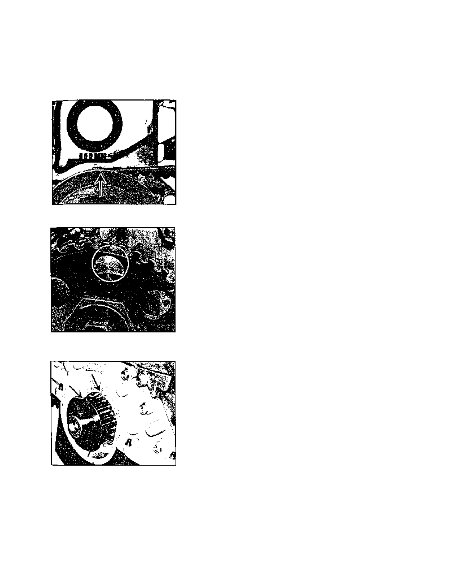
 

1】、Positioning no.1 cylinder top dead center    (compression) 


——Remove two M6×55 flange-shaped bolts, remove 
upper timing gear cover. 
——Install a wrench on crankshaft pulley bolt, rotate 

crankshaft Clockwise (viewed from the direction of pulley) 
until the TDC notch on crankshaft pulley aligns with the 
TDC mark (0) on timing gear cover. 

Note:Before rotation,spark plugs may be removed to 
reduce effort. 


——Check whether the TDC mark on the camshaft gear 
aligns with the mark on the front end of cylinder head. If 
not aligned, rotate crankshaft one turn,aligning the TDC 
mark on the camshaft gear with the TDC mark on the front 
end of cylinder head,engine should be at no.1 cylinder 
TDC . 
——With crankshaft pulley and lower timing gear 
removed,position no.1 cylinder at TDC as following: 

Rotate crankshaft, aligning the TDC mark on the 

crankshaft gear shaft with the TDC mark on the oil pump 
case. Check whether the TDC mark on camshaft gear 
aligns with the TDC mark on the front end of cylinder 
head. if not aligned, rotate crankshaft one turn,aligning 
the TDC mark on camshaft gear with the TDC mark on the 
front end of cylinder head. 


Fig.3 

Fig.2 

Fig.1 

PDF 文件使用 "pdfFactory Pro" 试用版本创建  


www.fineprint.com.cn

CAC Gasoline Engine Maintenance And Servicing Manual 

19 

2】、Upper and lower timing gear cover assemblies removal and installation 


Removal: 
——Loosen and remove 2 bolts for upper timing 
gear cover assembly. 
——Remove upper timing gear cover and seal 
assembly. 
——Remove seal gasket and shot nail from 
upper timing gear cover. 
——Remove crankshaft pulley. 
——Loosen and remove 2 bolts for lower timing 
gear cover assembly. 
——Remove lower timing gear cover and seal 
gasket assembly. 
——Remove shot nail and seal gasket from 
lower timing gear cover. 
Installation: 
——Clean lower timing gear cover. 
——Mount new seal gasket with shot nail or 
glue on lower timing gear cover. 
——Install lower timing gear cover and seal 
gasket on crankshaft,finger screw in 2 bolts and                                   

tighten to 9.0—11Nm. 
——Clean upper timing gear cover. 

——Mount new seal gasket with shot nail or glue 
on lower timing gear cover. 
——Install upper timing gear cover seal gasket 
with 2 bolts on cylinder block,tightening torque 
is 9—11Nm. 

3】、Crankshaft pulley removal and installation 


Removal: 
——If engine is equipped with starter,remove 
three M10×30 or M10×35 bolts and remove 
starter. 
——Block flywheel ring gear with a appropriate 
screwdriver or lever, preventing crankshaft from 
rotating. 
——Loosen crankshaft pulley mounting bolts, 
remove bolt and cushion block. 

——Pull out pulley, if necessary, puller may be   

used. 

upper timing gear cover assembly 

Bolt 

Tightening 
torque 

Tightening 
torque


Lower timing gear cover assembly

Fig.4 

Fig.5 
 

PDF 文件使用 "pdfFactory Pro" 试用版本创建  


www.fineprint.com.cn

CAC Gasoline Engine Maintenance And Servicing Manual 

20 

Installation: 
——Clean pulley and crankshaft journal,remove the 
oil in pulley groove . 
——Install pulley on crankshaft journal, aligning 
keyway with semicircular key. 
——Slip cushion block onto bolts and finger screw 
in. 
——Block flywheel ring gear with screwdriver, 
preventing crankshaft from turning. 
——Tighten bolts to 100—115Nm. 


4】、Valve cover and seal gasket removal and installation 


Removal: 
——Remove 9 bolts and butterfly gasket. 
——Remove valve cover and seal gasket 
assembly. 
——Remove seal gasket. 


B

u

tte

rf

ly

 w

a

sh

e

pulley 

Tightening torque 

bolt 

Valve cover 

Fig. 7 

V

a

lv

e


c

o

v

e

se

a

l g

a

sk

e

Fig.6 

Fig.8   

PDF 文件使用 "pdfFactory Pro" 试用版本创建  


www.fineprint.com.cn

CAC Gasoline Engine Maintenance And Servicing Manual 

21 

Installation: 

——Clean cylinder head and valve cover 
contacting surface. 
——Push the wedge of valve cover seal gasket 
into appropriate valve cover groove, 
integrating valve cover with seal gasket. 


——Install valve cover and seal gasket 
assembly on cylinder head. 
——Install 9 hexagon head bolts of long 
column end with butterfly gasket,finger screw 
them into cylinder head. 
——Tighten bolts in two steps in order as 
diagram showed. 

Step 1:Tighten to 4.0—6.0Nm 
Step 2:Tighten to 8.0—10.0Nm 


5】、Timing belt removal, installation and adjustment 

 
Removal: 
——Rotate crankshaft to no.1 cylinder compression TDC. 
——Loosen 2 tension pulley mounting bolt (as arrow 
indicated in diagram),push tension pulley aside with a large 
screwdriver. 
——To release belt tension,tighten 2 tension pulley mounting 
bolts with tension pulley in this position. 
——To reuse belt,mark the direction of belt rotation and 
make reference mark on crankshaft gear and camshaft gear 
matching teeth,remove belt from camshaft gear, water pump 
gear and crankshaft gear. 


Fig.11 

Fig.12 
 

Fig.9 

Fig. 10 

PDF 文件使用 "pdfFactory Pro" 试用版本创建  


www.fineprint.com.cn


Content   ..  23  24  25  26   ..