Chery SQR 7160 sedan. Manual - part 26


  Index      Chery     Chery SQR 7160 sedan - service repair manual


Search            


Content   ..  24  25  26  27   ..


Chery SQR 7160 sedan. Manual - part 26


CAC Gasoline Engine Maintenance And Servicing Manual 

22 

Note:With belt removed,  don't turn gear excessively,or piston 
head and valve may be damaged for contacting. 
——If belt need to be reused  ,check for improper 
wear ,delaminate crack (particularly at the foot of teeth) or dirt. If 
lightly suspected, replace it. 
Installation and adjustment: 
——Crankshaft should be positioned at no.1 cylinder TDC,if 
necessary, crankshaft may only be turned slightly for adjustment 
and blocked at flywheel ring gear. 
 
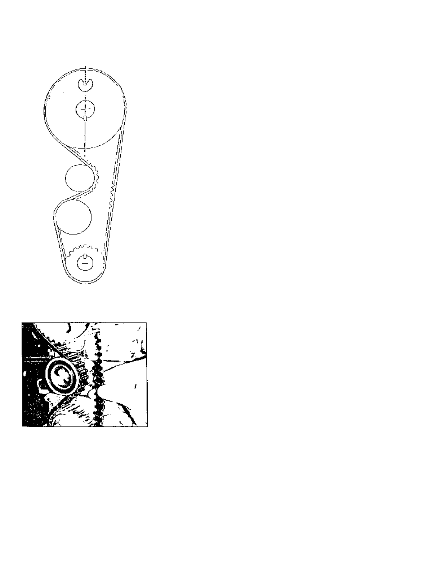
——Engage timing belt tooth with crankshaft grooves,and pull 
belt up straight to the right engaging belt with cam gear grooves.                 
During the installation of used belt, insure belt is in the right 
direction and match belt with appropriate tooth. 
With belt installed, 2 gears should not make any movement. 
——Pull belt around tension pulley carefully,engage belt tooth 

with gear teeth grooves. 
Recheck both gears, there should be no movement. 
——Loosen 2 tension pulley mounting bolts,push tension pulley 
right to the extreme (viewed from the direction of pulley ),

tighten 

2 tension pulley mounting bolts and loosen crankshaft locking 
device. 
——Rotate crankshaft clockwise (viewed from the pulley end) 2 
turns until no.1 cylinder reaches its TDC of compression. 
——Grab the midway of the right side belt between crankshaft 
gear and camshaft gear with thumb and forefinger. If belt tension 
is as specified, belt may be twisted 90°.                 
 
To adjust belt tension,loosen 2 tension pulley mounting bolts and 
push tension pulley right side using screwdriver as push rod,then 
tighten mounting bolts and rotate crankshaft.    Recheck tension. 
It may take 2- 3 times before tension is as specified. After 
adjustment, tighten tension pulley mounting bolts to 16—20Nm. 
 
——It is only a approximate method to adjust belt,and belt 
tension should be checked as soon as possible by professionals 
with special tools . 


Fig.13 

Fig.14 

PDF 文件使用 "pdfFactory Pro" 试用版本创建  


www.fineprint.com.cn

CAC Gasoline Engine Maintenance And Servicing Manual 

23 

 
6】、Tension pulley, crankshaft gear and camshaft gear removal, check and installation 

1.  Tension pulley 
Removal: 
——Rotate crankshaft to no.1 cylinder 
compression TDC. 
——Remove belt. 
——Loosen 2 tension pulley mounting bolts,
push tension pulley aside to release belt tension 
with a large    screwdriver. 
——Remove 2 mounting bolts and take out 
tension pulley. 
Installation: 
——Check bearing for rotating freely by     

turning tension pulley,bearing end play and 
radial        clearance, if suspected, replace 
appropriate parts    immediately. 
——Crankshaft should be positioned at no.1 
cylinder compression TDC. 
——Install belt tension pulley,finger screw in 2                         
mounting 

bolts, 

then 

tighten 

to 

16—20Nm.2.Camshaft gear.


Removal: 
——Rotate crankshaft to no.1 cylinder 
compression TDC 

          ——Remove belt. 

——Insert a lever into one of the camshaft gear 
holes  to  block  camshaft,then  loosen  gear  bolt 
and remove bolt and cushion block.


Note:During reinstallation,new bolt should be 
applied , remove camshaft gear.


——Camshaft  gears  are  not  permitted  to  be 
exchanged between 478 engine and 480 engine,
during  replacement,  the  mark  on  the  original 
gear should be referred.


Crankshaft gear 

Tension pulley 

Timing gear 

key 

cushion 

Bolt M12*1.5*30 
Tightening torque52-60n.m 

key 

Bolt M8*25 
Tightening 
torque16-20Nm 

Fig.15 

Fig.16 
 

PDF 文件使用 "pdfFactory Pro" 试用版本创建  


www.fineprint.com.cn

CAC Gasoline Engine Maintenance And Servicing Manual 

24 


Installation:


——Check gear tooth for wear, pitting or scratch. 
——Install camshaft semicircular key,protrusion should 
be 1.64—2.11mm. 
——Install camshaft gear on camshaft with new   
bolt though cushion block,new bolt should be       
pre-pasted and tightened to 52—60Nm.——Check 
whether crankshaft is positioned at compression TDC. 
 
3.Crankshaft gear 
Removal: 

——Block crankshaft and remove belt. 

——Pull out crankshaft gear with puller or 2 large 
screwdrivers,then remove semicircular key. 

Installation: 
——Check gear tooth for wear, pitting or scratch. 

——Install semicircular key,protrusion should be 
1.392—1.739mm. 

——Install shim with curved face side forward. 

——Install crankshaft gear with boss side forward, and 
then press crankshaft gear onto boss using a assistant 
pulley and pulley bolt. 

 
7】、Camshaft oil seal removal and installation 

 
Removal: 
——Remove camshaft gear. 
——Note the direction of oil seal installation, pry out oil 
seal from the oil seal hole in cylinder head,be sure not 
damage the oil seal hole. 
Installation: 
——Clean the oil seal hole in cylinder head ,apply clean 
engine oil on oil seal edge and camshaft oil seal journal,
install oil seal on oil seal journal carefully,push oil seal 
in perpendicularly into place with a appropriate cushion 
block and used camshaft gear bolt. An appropriate socket 
wrench may be used to push oil seal into place. 


Fig.17 

Fig.18 

PDF 文件使用 "pdfFactory Pro" 试用版本创建  


www.fineprint.com.cn

CAC Gasoline Engine Maintenance And Servicing Manual 

25 

8】、Valve mechanism and cylinder head removal, check and installation 
1.Valve mechanism for 478 and 480 engine: 


Rocker arm-8 

Valve locking piece-16 

Rocker arm seat-8 

Fit 

clearance 

with 

hole 

0.023/0.065   

Rocker arm stud-8 

Tightening torque 18-23Nm 

Upper Valve spring seat -8   

Valve spring -8


Valve oil seal spring seat assy-8 

Assembly  before  valve  oil  seal 
spring and valve installation 

Rocker arm seat washer-8 

hydraulic lifting rod-8 

Rock  arm  nut-8  .tightening  torque 
25-29n.m 

Exhaust  valve-4.  fit  clearance  between  left  valve 
stem and valve guide is 0.046-0.095 

Intake  valve-4.  fit  clearance  between  valve 
stem and valve guide is 0.02-0.069 

Fig.19   

PDF 文件使用 "pdfFactory Pro" 试用版本创建  


www.fineprint.com.cn


Content   ..  24  25  26  27   ..