Chery S11 / Chery QQ. Manual - part 119


  Index      Chery     Chery S11 / Chery QQ - service repair manual


Search            


Content   ..  117  118  119  120   ..


Chery S11 / Chery QQ. Manual - part 119


Chery QQ Service Manual     


Mechanical Part of SQR 472Engine


45 

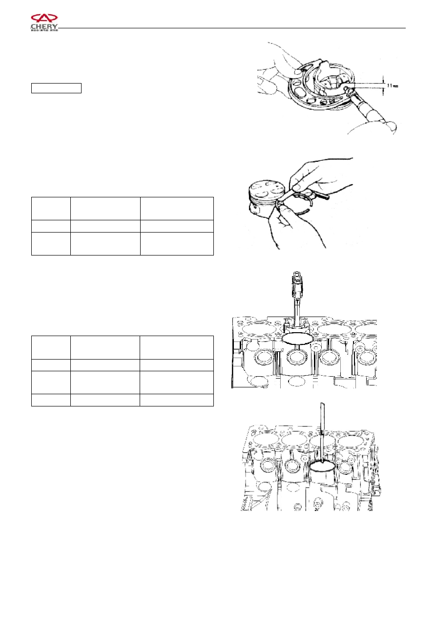
4.2.4    Measure the diameter of the piston 

4.2.4.1 

Measure  at  about  11  mm  to  the  bottom  of  the 

piston, along the direction vertical to the piston pin. 

Standard value

72

013

.

0

025

.

0

φ

-

-


4.2.5    Inspect  the  clearance  between  the  piston  ring  and 

the ring gloove 

4.2.5.1 

Measure  around  the  ring  gloove  with  a  piston 

ring and a feeler gauge 


Standard value 

(mm) 

Limit   

(mm) 

First ring 

0.03~0.06


0.12 

Second 

ring 

0.03~0.06


0.11 


4.2.6 

Inspect the end clearance of piston ring 

4.2.6.1 

Put  the  piston  ring  45mm  below  the  top  surface 

of  the  cylinder  hole.  Press  down  the  piston  ring  with  the 

piston  head,  and  then  measure  the  opening  with  a  feeler 

gauge. 


Standard value 

(mm) 

Limit   

(mm) 

First ring 

0.25-0.40 

0.65 

Second 

ring 

0.35~0.50


0.65 

Oil ring 

0.20~0.70


1.00 


Chery QQ Service Manual     


Mechanical Part of SQR 472Engine


46 


4.2.7 

Inspect  the  clearance  between  the  piston  and 

cylinder wall 

4.2.7.1 

Measure  the  inner  diameter  of  the  cylinder  and 

the  outer  diameter  of  the  piston  at  the  positions  as 

indicated  in  the  right  figure.  If  the  measurement  results 

exceed the limit, replace the piston or cylinder.   

Standard value:  0.018~0.030 

Limit

0.10 

[Reference] The clearance between the piston and cylinder 

bore is  controlled by the  difference between the  minimum 

inside  diameter  of  piston  hole  and  the  maximum  outer 

diameter of piston. 

4.2.7.2 

After  replacing  the  piston  or  the  cylinder  body, 

confirm the clearance again 

Standard value:  0.018~0.030 


4.3    Crankshaft 

4.3.1    Inspect  the  proper  alignment  of  the  main  axle 

diameter. 

4.3.1.1 

Measure the proper alignment with a dial gauge, 

if  the  proper  alignment  is  beyond  the  limit,  replace  the 

crankshaft. 

Limit

0.03mm 

Notice:  The  bending  value  should  be  equal  to 

one-second  the  run-out  value  of  crankshaft  rotating  one 

circle. 

4.3.2 

Inspect the crankshaft for the abrasion. 

4.3.2.1 

Measure  the  connecting  rod  journal  at  the 

positions  indicated  in  the  left  figure  with  a  microcaliper, 

and figure out the roundness and cylindricity. 

Limit

0.005mm 


4.3.2.2 

Measure  the  connecting  rod  journal  at  the 

positions  indicated  in  the  right  figure  with  a  microcaliper, 

and figure out the roundness and cylindricity. 

Limit

0.004mm 


5  Assembly  of  Crank  Connecting  Rod 

mechanism 

5.1  Assembly of the piston connecting rod 


Measurement  position  of  piston 

Outer Diameter 

Measurement 

position  of  piston 

Inner Diameter 


Chery QQ Service Manual     


Mechanical Part of SQR 472Engine


47 

5.1.1 

Assemble  the  piston,  connecting  rod  and  the 

piston  pin  with  special  tool  following  the  instructions 

below: 

5.1.1.1 

Spread  engine  oil  over  the  pin  hole  of  the 

connecting rod, assemble according to the group mark and 

direction mark of piston and connecting rod. 


5.1.1.2 

Assemble the piston and the connecting rod with 

special tools shown in the right figure. 


5.1.1.3 

Adjust  and  assemble  the  piston  and  connecting 

rod  as  indicated  in  the  right  figure.  Spread  the  piston  pin 

with  oil  and  then  assemble  the  piston  and  connecting  rod 

with a oressing machine. 


Notice:  When  pressing  in  the  piston  pin,  make  sure  the 

fitting direction is correct. 

·When  the  piston  pin  is  pressed  into  the  piston,  the 

small  end  of  the  connecting  rod  should  be  heated 

to 300

, and the pin should be aligned properly. 


5.2  Install the first and second pistion ring and the oil ring 

according to the following instruction: 

5.2.1    Installation of piston ring 

Make  the  side  with  marks  face  upwards,  and  then  fix  it 

with piston pin tools. 


5.2.2 

Mount the steel tape  combined  oil ring (bushing 

ring  lower,  lower  blade,  upper  blade)  firstly,  and  then 

mount the second  gas ring, and  finally  mount the  first  gas 

ring. Opening angles of rings are shown in the figure: 


Mark Forward 

Align and Straight 

Mark   

1

st

 Ring   

2nd Ring   

Oil Ring   

Lower Blade


1

st

 Ring   

2nd Ring   

Front 

Bushing 

Ring   

Rear   

Upper Blade


Section Shape   


Chery QQ Service Manual     


Mechanical Part of SQR 472Engine


48 

5.3    Resemble  the  crankshaft  main  bearing  cap, 

crankshaft,  crankshaft  bearing  bushing  and  the  crankshaft 

axial thrust plate, pay attention to the following: 

5.3.1    Assembling  the  bearing  bushing,  its  raised  thrust 

block  should  fit  into  the  locating  groove  in  the  cylinder 

body. 

Notice:  The  bearing  bushing  is  from  the  same 

manufacturer. 


5.3.2    Spread  the  crankshaft  bearing  bushing  (upper 

piece) with oil before assemble the crankshaft 


5.3.3    Mount the thrust plate on the cylinder body bearing 

base  and  make  sure  that  the  side  with  oil  gloove 

(crankshaft shank) face outwards. 

Notice:  Spread the side of oil glove with oil 

5.3.4    Fix  the  crankshaft  bearing  bushing  (lower  piece)  in 

the  bearing  cap,  the  bearing  bushing  should  fit  into  the 

thrust groove. 


5.3.5    Spread  engine  oil  over  the  friction  surface  of 

crankshaft  bearing  bushing  (lower  piece),  assemble  the 

bushing  according  to  the  mark  forwards  in  the  main 

bearing cap of the crankshaft. 


5.3.6    Spread oil over the bolts, within three or two times, 

tighten them with specified torque. 

Torque:  70±3.5N.m     


5.3.7    Rotate  the  crankshaft  after  assembly,  it  should 

rotates  swiftly,  the  rotating  torque  should  be  less  than 

1Nm. 


Thrust Plate


Oil Tank


Spread  Oil  on  the  surface  of 

Bearing Bushing 

Outer  Forward  of  Oil 

Tank 

Forward Mark


Axle Diameter Mark


Content   ..  117  118  119  120   ..