Chery S11 / Chery QQ. Manual - part 117
Chery QQ Service Manual
Mechanical Part of SQR 472Engine
37
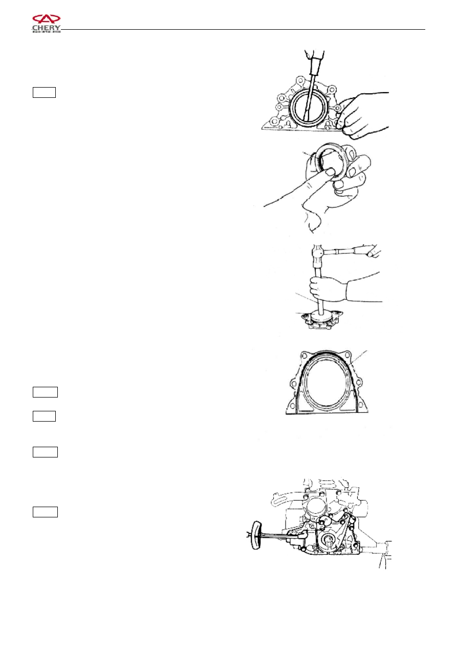
5.2 Disassembly
5.2.1 Remove the rear crankshaft oil seal with a
screwdriver.
Notice: The rear oil seal of the crankshaft is nonreusable.
5.3 Inspection
Inspect the oil seal for damage and the abrasion at its lip.
5.4 Assembly of oil seal
5.4.1
Spread engine oil over the lip of the new oil seal.
5.4.2
Mount the oil seal with special tool as indicated
in the right figure
6. Assembly
6.1 Assembly of the oil seal seat
Spread sealant over the oil seal seat as shown in the right
figure.
Grease: Loctite 5699
Notice: Spread the liquid sealant on the position of the
oil seal base which is to contact with the cylinder body,
and make sure the width of the sealant is 3-4mm.
Torque: 25±1.5N.m
6.2 Assembly of the new engine oil pump gasket and the
engine oil pump assembly.
Torque: 20±1.5N.m
6.3 Assemble the new engine oil collector gasket and the
Special Tool
Special Tool
Glue Spread Line
Lip