Chery QQ6 (S21) / S12LHD. Manual - part 241


  Index      Chery     Chery QQ6 (S21) / S12LHD - service repair manual


Search            


Content   ..  239  240  241  242   ..


Chery QQ6 (S21) / S12LHD. Manual - part 241


29 


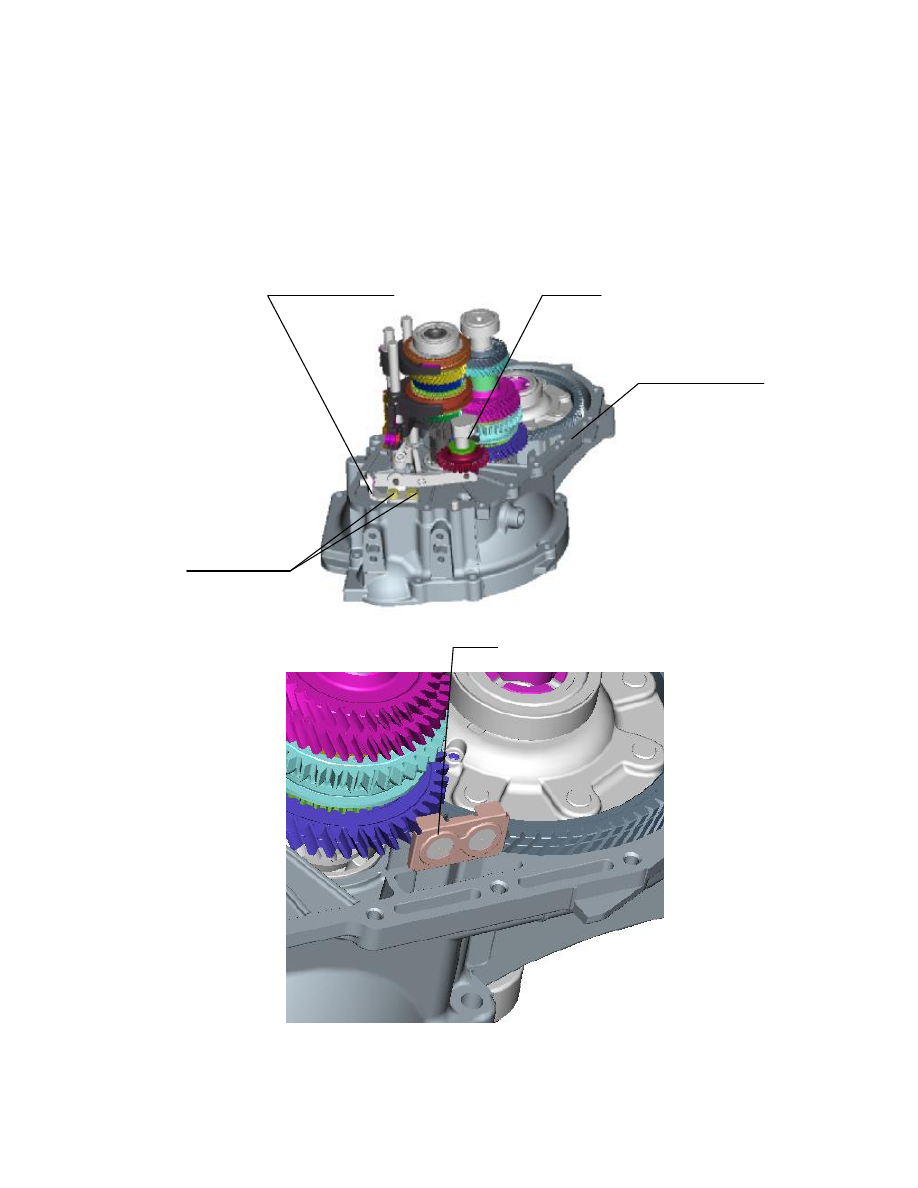
        Install the assembled idler assembly (assembly  of idler  assembly is  comparatively  simple, please refer 

to its disassembly process) onto clutch housing, and then install reverse gear fork mechanism assembly with 

tightening  torque  of  the  two  reverse  gear  rocker  arm  bracket  bolts  as  25±2Nm.  Clean  the  junction  part  of 

clutch  and  transmission  housings  and  apply  sealant  (oil  resistance  silicone  sealant,  HZ1213Q/320222 

YAP02-92) on it, and then install the magnet. See Figure 30.       


Reverse gear fork mechanism assembly    Idler assembly 


Magnet 


Figure 30 

Apply sealant on junction part 

of  clutch  and  transmission 

housings 

倒档摆臂支架

螺栓(拧紧力
矩 25±2Nm

30 


Assemble transmission housing and clutch housing together and then fasten them with connecting bolts. 

Before  fastening,  apply thread  locking  glue (262 type  anaerobic adhesive)  on the bolts properly. Tighten 

the diagonal bolts first as possible to ensure favorable fastening and sealing effects, and the tightening torque 

for the bolts are 25±2NmNote: the two connecting bolts at oil drain hole are a little longer than  other 

connecting bolts, and the bracket should be installed first. See Figure 31. 


Figure 31 


To install the assembled gearshift mechanism assembly onto the transmission, clean the junction part of 

gearshift  housing  and  transmission  housing  and  apply  sealant  on  it  (oil  resistance  silicone  sealant, 

HZ1213Q/320222 YAP02-92), align one end of gearshift shaft with the linear bearing inside the transmission 

and  align  the  locating  hole  on  gearshift  housing  with  the  locating  pin  on  transmission  housing,  and  then 

tighten  the  connecting  bolts  of  gearshift  housing  and  transmission  housing  with  the  tightening  torque  as 

25±2Nm. See Figure 32. 

Reverse  gear rocker arm bracket bolt 

(with tightening torque as 25±2Nm

Connecting bolt of transmission and clutch housings (13) 

Bracket 

The  two  connecting 

bolts are longer 

31 

Connecting bolts of gearshift housing and transmission housing 

(5, tightening torque: 25±2Nm


Figure 32 

9. Disassembly of external accessories of transmission 

Respectively install locating seats of 1/2 gears fork shaft and 3/4/5 gears fork shaft. Before installation, 

apply thread fastening glue (262 type anaerobic adhesive) on the thread, and the tightening torque for the 

bolts are 20±2NmNote: the locating seat of 1/2 gears fork shaft is longer than that of 3/4/5 gears  fork 

shaft. Then install locating seat of gearshift shaft, before installation, apply thread fastening glue (262 type 

anaerobic adhesive) on the thread, and the tightening torque for the bolts are 32±2.5Nm; and install backup 

lamp  switch  assembly,  before  installation,  apply  thread  fastening  glue  (262  type  anaerobic  adhesive)  on 

the thread, and the tightening torque for the bolts are 20±2Nm. See Figure 33.   


Locating  seat  of  gearshift  shaft  (with 

tightening torque as 32±2.5Nm

Switch  assembly  of  backup  light

(with 

tightening 

torque 

as 

20±2Nm

Locating  seat  of  3/4/5  gears  fork  shaft 

(with tightening torque as 20±2Nm

Locating  seat  of  1/2  gears  fork  shaft 

(with tightening torque as 20±2Nm


32 

                                                                  Figure 33 

        Follow  by  installation  of  screw  of  reverse  gear  idler  shaft.  Align  the  screw  of  reverse  gear  idler  shaft 

with the threaded  hole  on the idler shaft, and then tighten it  with the tightening torque as  38±2.5Nm;  after 

that,  tighten  bleeding  plug  with  tightening  torque  as  44±3Nm;  finally,  install  oil  limit  plug  onto  the 

transmission, but do not tighten it then. See Figure 34. 


Figure 34 

10. Refilling and volume regulation of transmission lubricant 

After the transmission is installed onto the vehicle, park the vehicle on a flat road surface, then use the 

tool  for refilling to  refill  transmission  lubricant. The lubricant  refilled should at least conform to API  GL-4 

SAE 75W-90 specification. Refill  through  installation  hole  of speed sensor as shown  in  Figure 35  with  the 

refilling volume as 1.8L. after refilling, open the oil limit plug to regulate the lubricant to specified volume, 

and then tighten the oil limit plug with the tightening torque as 44±3Nm

Oil-Limiting Plug 

Screw  of  reverse  gear  idler  shaft  (with 

tightening torque as 38±2.5Nm

Bleeding plug (with tightening torque 

as 44±3Nm


Content   ..  239  240  241  242   ..