Chery A18. Manual - part 88
 

  Index      Chery     Chery A18 - service repair manual


Search            


Content   ..  86  87  88  89   ..


Chery A18. Manual - part 88


131 

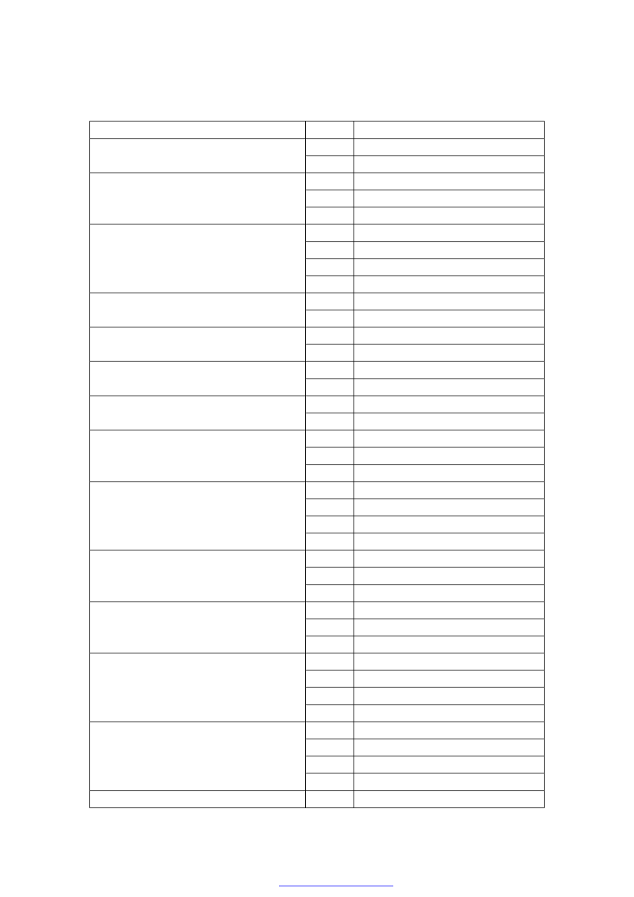
II. Main plug-in units explanation 

Name of plug-in unit 

Pin No. 

Origin 

1 

Main relay 

Plug-in unit of carbon tank electromagnetic valve   

2 

ECU 

1 

ECU 

2 

Pressure sensor 

Plug-in unit of throttle position 

3 

ECU 

1 

ECU 

2 

ECU 

3 

ECU 

Plug-in unit of stepper motor 

4 

ECU 

1 

Main relay 

Plug-in unit of the nozzle 1 

2 

Main relay 

1 

Main relay 

Plug-in unit of the nozzle 2 

2 

ECU 

1 

Main relay 

Plug-in unit of the nozzle 3 

2 

ECU 

1 

Main relay 

Plug-in unit of the nozzle 4 

2 

ECU 

1 

ECU 

2 

ECU 

Shock sensor 

3 

— 

1 

ECU 

2 

ECU 

3 

ECU 

Pressure sensor 

4 

ECU 

1 

ECU 

2 

ECU 

Rotation speed sensor 

3 

— 

1 

Main relay 

2 

ECU 

Phrase sensor 

3 

ECU 

1 

ECU 

2 

ECU 

3 

ECU 

Ignition   

4 

— 

1 

Main relay 

2 

ECU 

3 

ECU 

Oxygen sensor (2) 

4 

ECU 

Main relay 

1 

132 

2 

Main relay 

3 

— 

4 

Main relay 

5 

— 

6 

Accumulator anode 

7 

— 

8 

Fuse 


9 

— 

1 

— 

2 

Fuse 

3 

— 

4 

ECU 

5 

— 

6 

Main relay 

7 

— 

8 

Plug-in unit of the fuel pump & A/C 

Fuel pump relay 

9 

— 

1 

Main relay 

15A fuse 

2 

Fuel pump relay 

1 

Accumulator anode 

30A fuse 

2 

Main relay 

1 

Accumulator anode 

7.5A fuse 

2 

ECU 

1 

plug-in unit if the machine fuel pressure   

2 

ECU 

3 

Plug-in against theft & of the speed signal 

4 

Plug-in against theft & of the speed signal 

5 

ECU 

6 

ECU 

7 

ECU 

8 

ECU 

9 

ECU 

10 

ECU 

11 

Plug-in unit of the fuel pump & A/C 

12 

Plug-in unit of the fuel pump & A/C 

13 

ECU 

14 

Plug-in unit of the fuel pump & A/C 

15 

Plug-in unit of the fuel pump & A/C 

Interface plug 

16 

— 


133 

III. Disassembly & assembly of the engine wiring harness 

Part No.:A18-3724180BA 

(I).Preparation 

Tools: 

Socket wrench 10#, Phillips screwdriver, slotted screwdriver 

(II).Attention 

Firstly  cutting  the  power  is  a  must  before  disassemble 

electric components & wiring harness. 

The ignition switch must be in a close state. 

(III).

Disassembly steps


3.1. Please open the front compartment firstly 

3.2.  Disassemble  the  connecting  wire  with  the 

positive  electrode  of  the  accumulator  with  the 

wrench 10# 


3.3.  Please  disassemble  ECU  protective  cover  and 

take out the plug-in unit with ECU 


3.4. Please take  out  the  plug-in  unit  with the  pressure 

sensor or the air intake 


134 

3.5. Take out the plug-in unit with the stepper motor   


3.6. Take out the plug-in unit with the throttle   


3.7. Take out the plug-in unit with the ignition coil 


3.8. Take out the plug-in unit with the phase sensor 


3.9.  Take  out  the  plug-in  unit  with  the  cooling 

temperature sensor 


Content   ..  86  87  88  89   ..