Acura RSX Honda Integra. Manual - part 121
04
05
−
−
−
−
−
−
−
−
YES
NO
YES
NO
YES
NO
YES
NO
11-190
PGM-FI System
DTC Troubleshooting (cont’d)
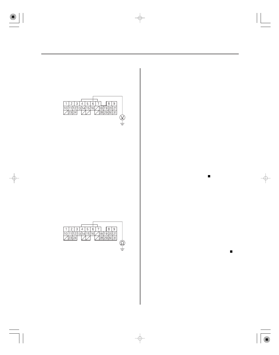
CMPB (GRN)
ECM/PCM CONNECTOR A (31P)
CMPB (GRN)
ECM/PCM CONNECTOR A (31P)
11. Measure voltage between ECM/PCM connector
terminal A6 and body ground.
Repair open in the wire between the ECM/
PCM (A6) and CMP sensor B, then go to step 18.
Go to step 12.
12. Turn the ignition switch OFF.
13. Jump the SCS line with the HDS.
14. Disconnect ECM/PCM connector A (31P).
15. Check for continuity between ECM/PCM connector
terminal A6 and body ground.
Repair short in the wire between the ECM/
PCM (A6) and CMP sensor B, then go to step 18.
Go to step 24.
16. Turn the ignition switch OFF.
17. Replace CMP sensor B (see page 11-281).
18. Reconnect all connectors.
19. Turn the ignition switch ON (II).
20. Reset the ECM/PCM with the HDS.
21. Do the ECM/PCM idle learn procedure (see page
11-349).
22. Start the engine.
23. Check for Temporary DTCs or DTCs with the HDS.
If DTC P0365 is indicated, check for poor
connections or loose terminals at CMP sensor B
and the ECM/PCM, then go to step 1. If any other
Temporary DTCs or DTCs are indicated, go to the
indicated DTC’s troubleshooting.
Troubleshooting is complete.
24. Update the ECM/PCM if it does not have the latest
software, or substitute a known-good ECM/PCM
(see page 11-6).
25. Check for Temporary DTCs or DTCs with the HDS.
If DTC P0365 is indicated, check for poor
connections or loose terminals at CMP sensor B
and the ECM/PCM, then go to step 1. If any other
Temporary DTCs or DTCs are indicated, go to the
indicated DTC’s troubleshooting.
If the ECM/PCM was updated, troubleshooting
is complete. If the ECM/PCM was substituted,
replace the original ECM/PCM (see page 11-284).
Wire side of female terminals
Wire side of female terminals
Is ther e about 5 V ?
Is ther e continuity?
Ar e any T empor ar y DT Cs or DT Cs indicated?
Ar e any T empor ar y DT Cs or DT Cs indicated?
05/06/27 17:35:48 61S6M040_110_0190